{"authorId":"","cover":"/content/images/2016/08/IMG_7487.jpg","heroes":{"8060d348c89d6a36c962a8c289b54bab":"/content/images/2017/03/IMG_0381.JPG","bfd1ec8875b9ff5807a23c1e5275e668":"/content/images/2017/06/IMG_1248.jpg"},"kind":"tag","logo":"/content/images/2016/08/projectable-me-4.png","nav":[{"id":"62e854d471683dea63488bcbca5c6188","label":"Home","url":"/","sortOrder":0},{"id":"1bc84fb15620acd635df7735a0b8ddd8","label":"Raspberry Pi","url":"/tag/raspberry-pi/","sortOrder":1},{"id":"3207e2fec51d66d2a5b3d8d04feb9dd8","label":"Sim Racing","url":"/tag/sim-racing/","sortOrder":2},{"id":"59115afd52e59a74faa4b386e00ae3fa","label":"About","url":"/about-me/","sortOrder":3}],"page":1,"perPage":10,"posts":[{"id":"bfd1ec8875b9ff5807a23c1e5275e668","siteId":"projectable","slug":"my-sim-racing-motion-rig-version-2","title":"My sim racing motion rig version 2","markdown":"I have really enjoyed having a motion simulator platform for sim racing. It's fairly close to real world racing, but costs a LOT less money, and there isn't that risk of serious injury, or death ☠️\n\nI started down this path almost 3 years ago, and with the Oculus Rift bringing VR in to the picture, I am truly hooked.\n\nVersion 1 of the motion rig was thrown together using 80/20 extrusion that I already had, and it was pieced together without any real planning. One of the biggest drawbacks of version 1 was its inability to easily adjust for other drivers, especially my kids. There were a few other shortcomings: it was uncomfortable, it flexed and squeaked, the rear traction loss wasn't smooth, the rear speakers flopped around like crazy, and so on...\n\n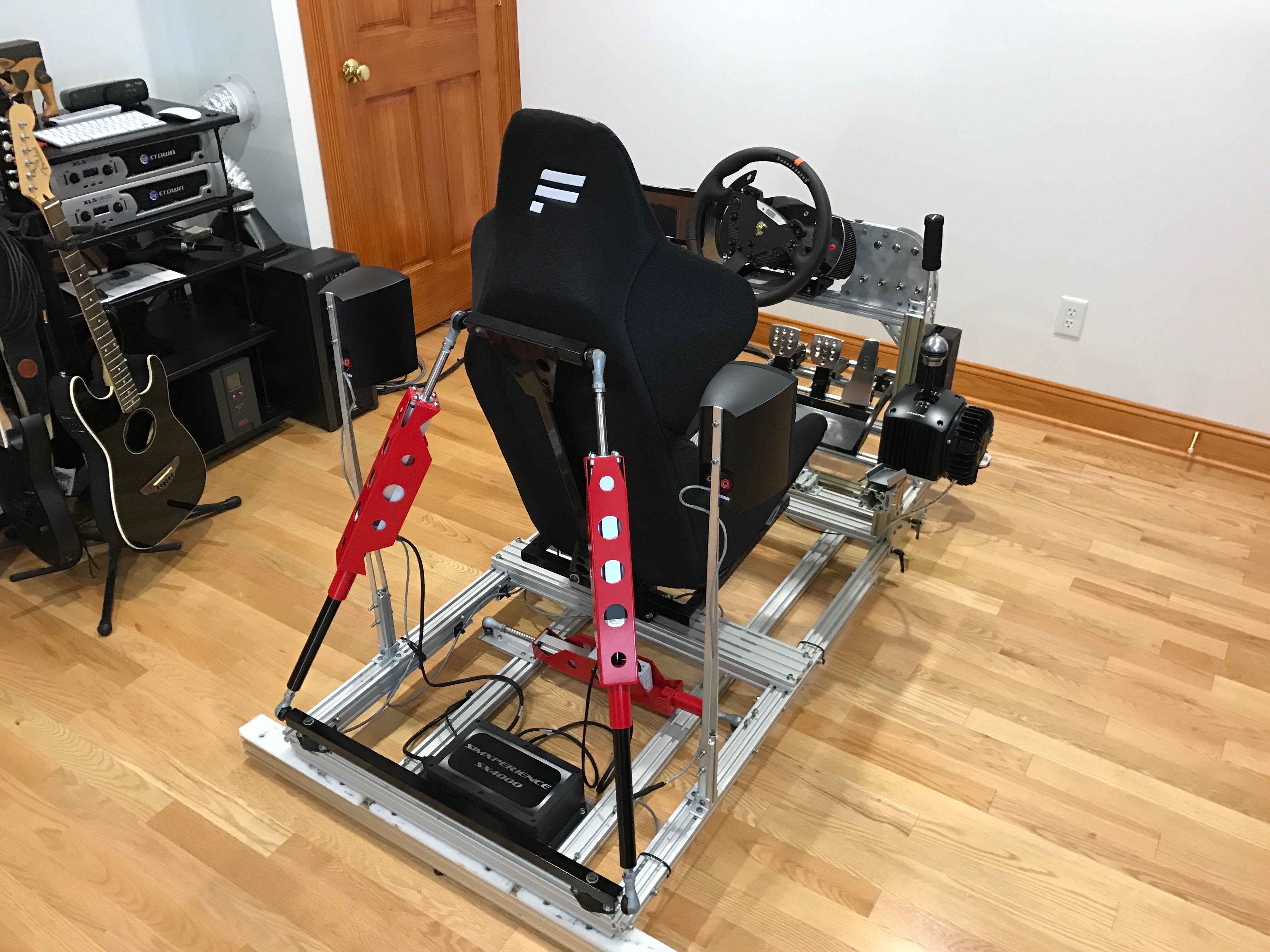\n\nI decided to spend a little while thinking about how to best resolve the big issues, and turned to Fusion360 to design a quick mockup of the main features.\n\n\u003cp align=\"center\"\u003e\n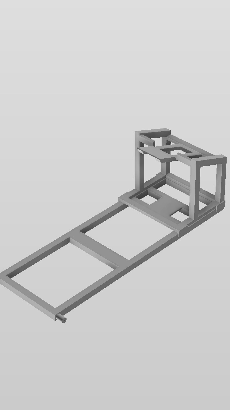\n\u003c/p\u003e\n\nThe new design became the basis of what I ordered from [80/20 Inc](https://8020.net): Extrusion, linear movement components for the sliding top frame, and the hinges for the steering bracket.\n\nOnce the extrusion arrived, I quickly mocked up how everything would fit together and came up with an implementation plan.\n\n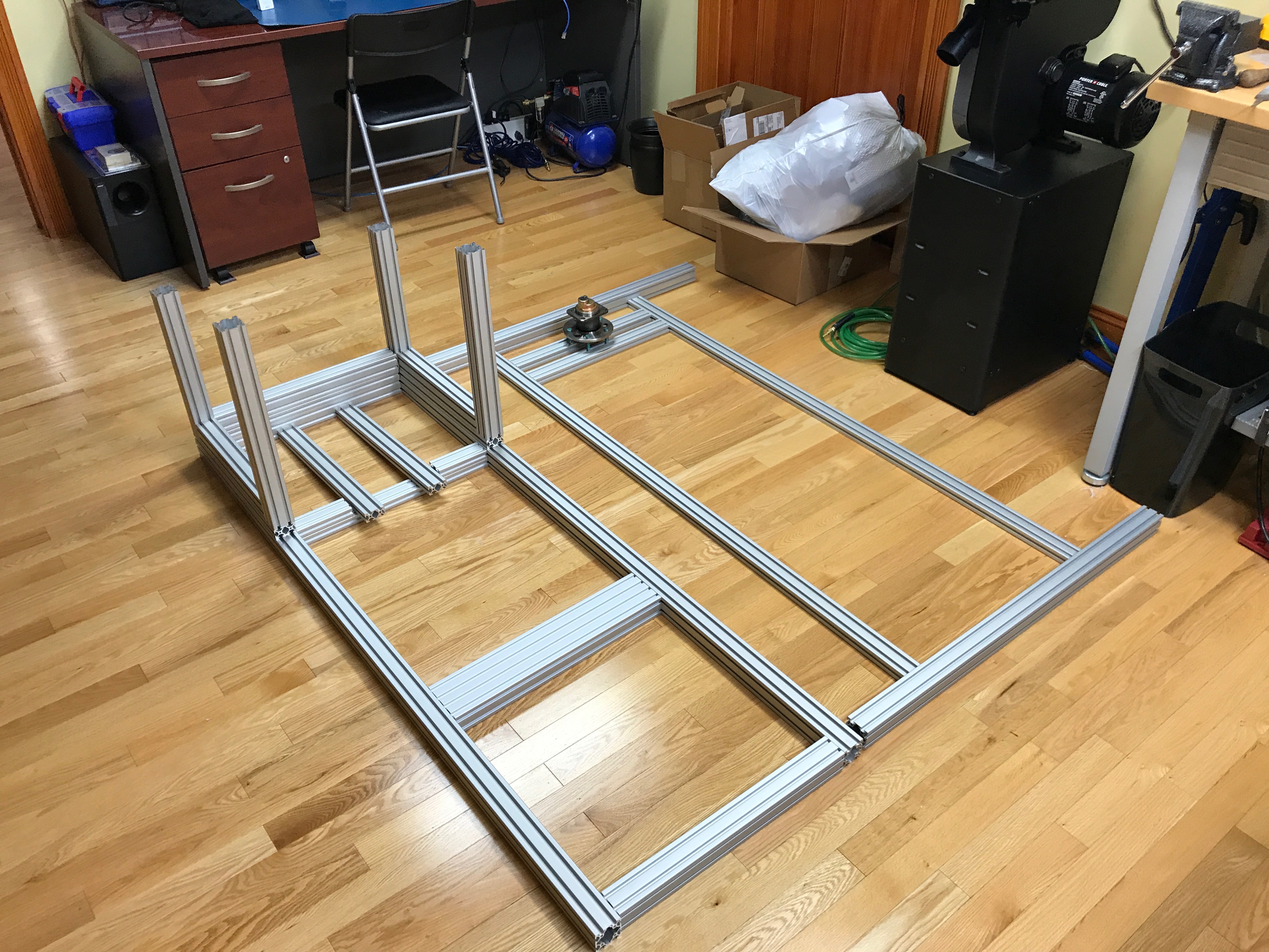\n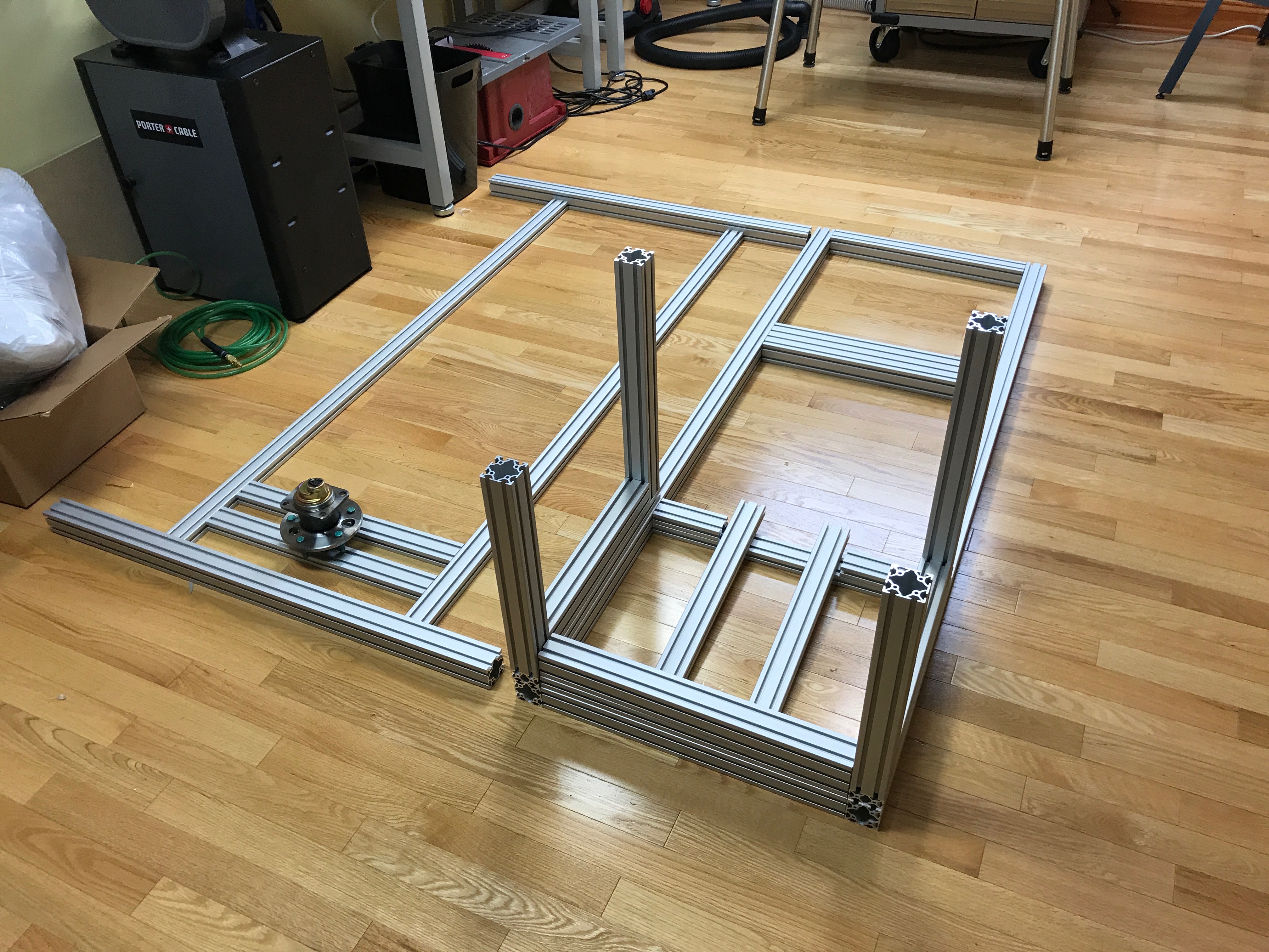\n\nStarting with the lower frame, I came up with a process of thread tapping, drilling, and milling to piece everything together.\n\n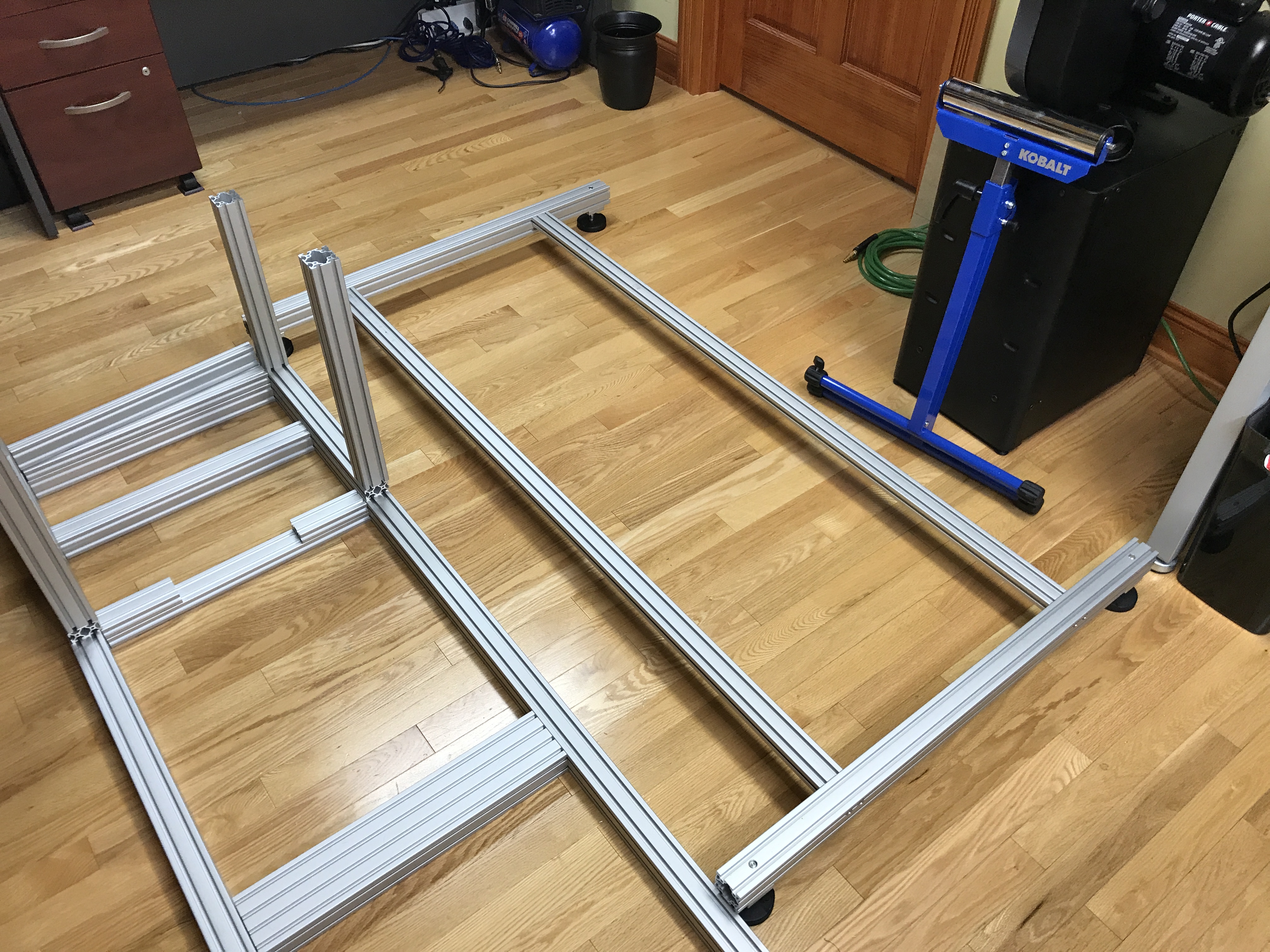\n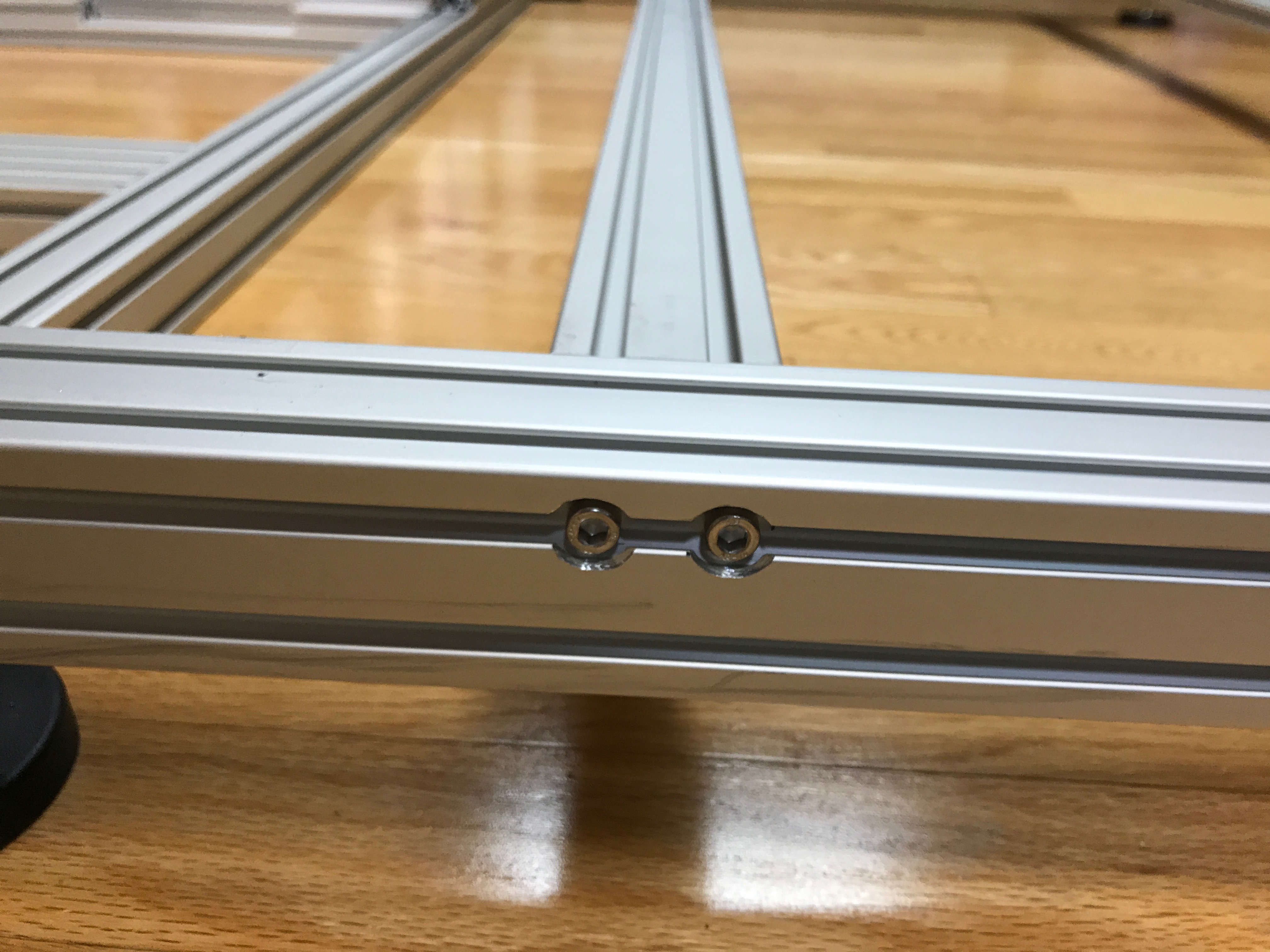\n\nUsing a mill bit in my drill press, I was able to notch out the recesses so that the bolt heads sat flush to the edge of the extrusion.\n\n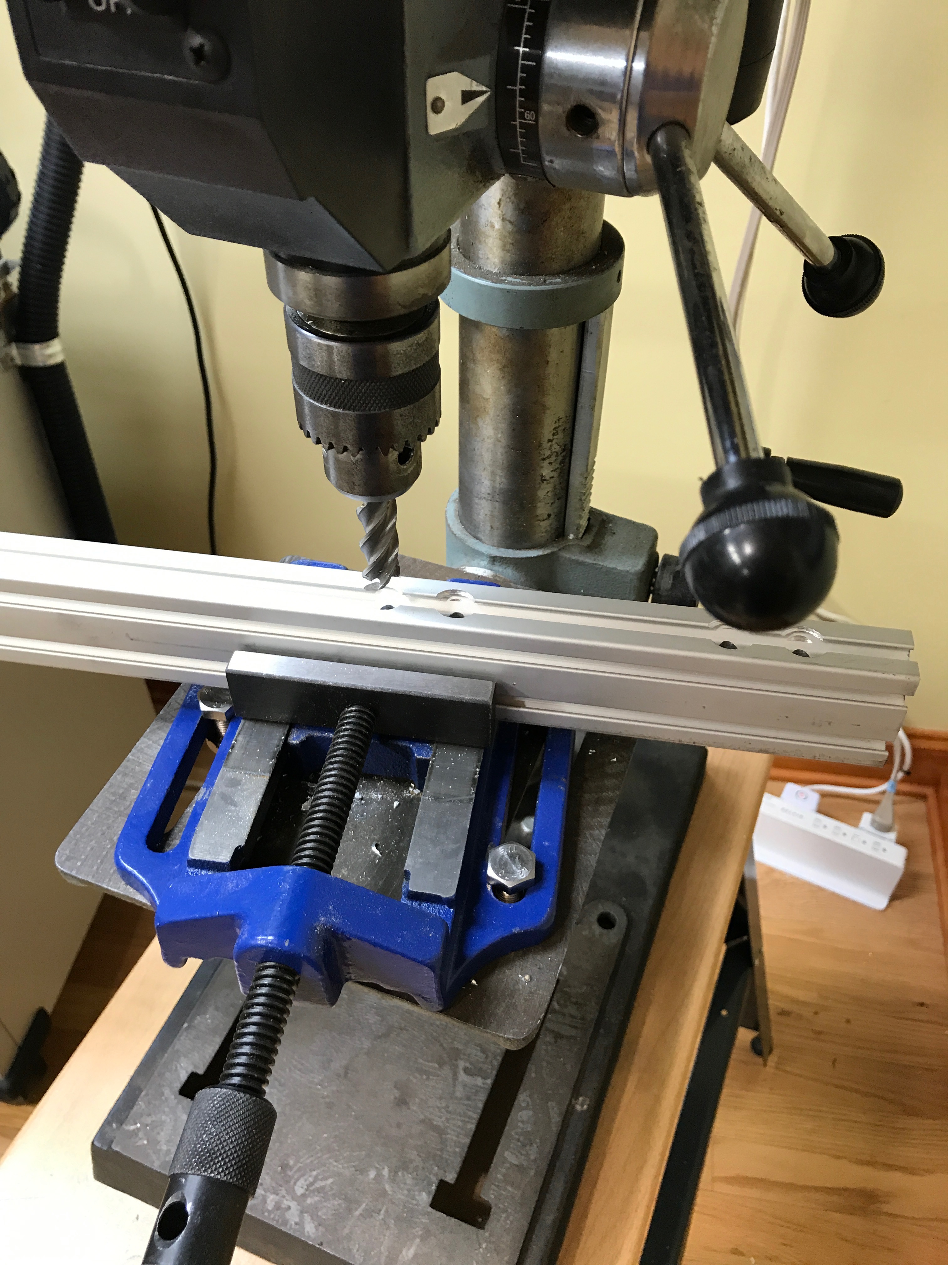\n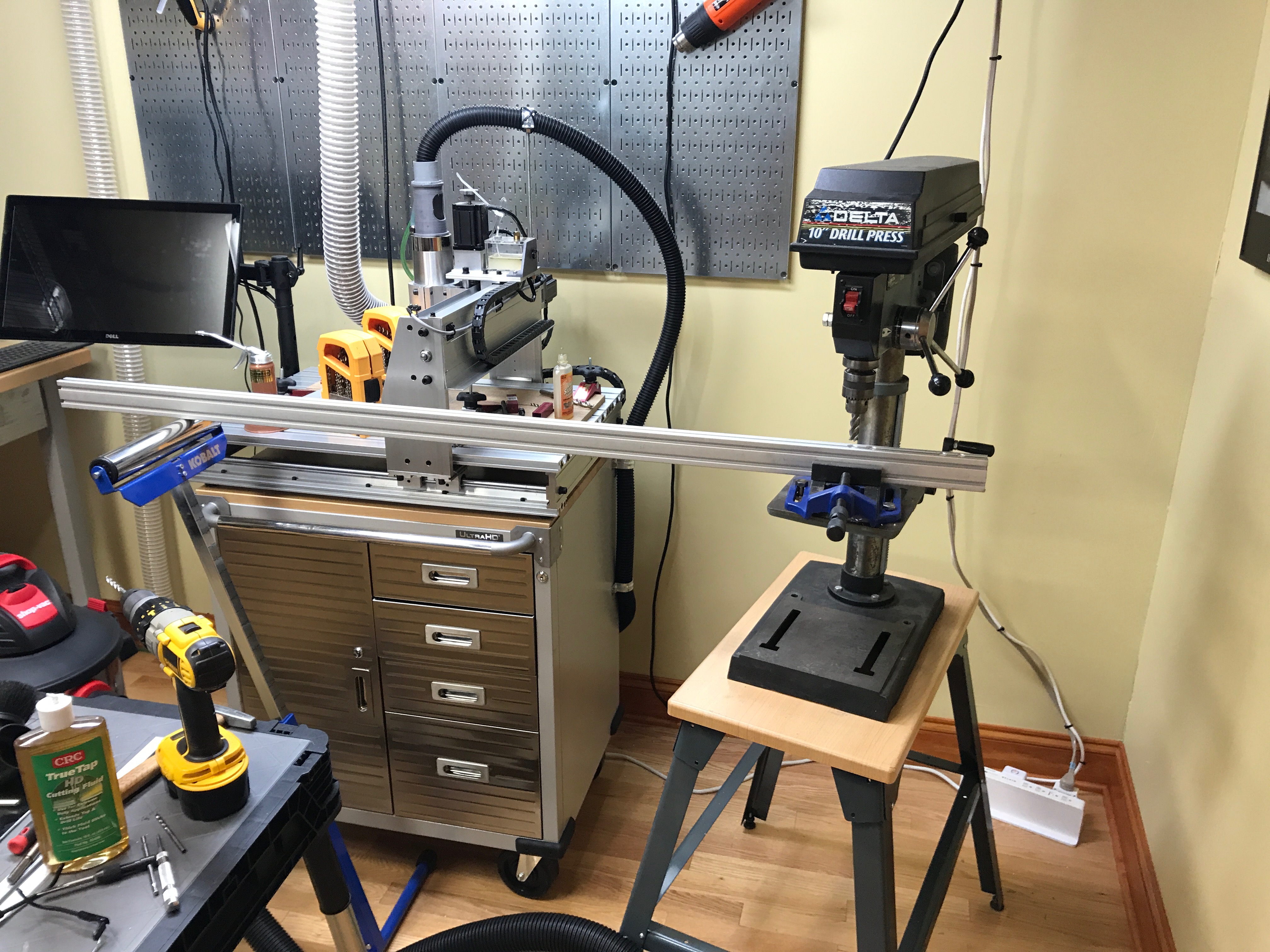\n\nThis worked out nicely, although my drill press was a little too loose to provide the most accurate cutting. The drill shaft moved all over the place, leaving some of the recesses a little out of alignment.\n\nNext was building the mid frame joint. The lower and mid frames were attached together using a GM wheel hub that I picked up on eBay for $20 shipped.\n\n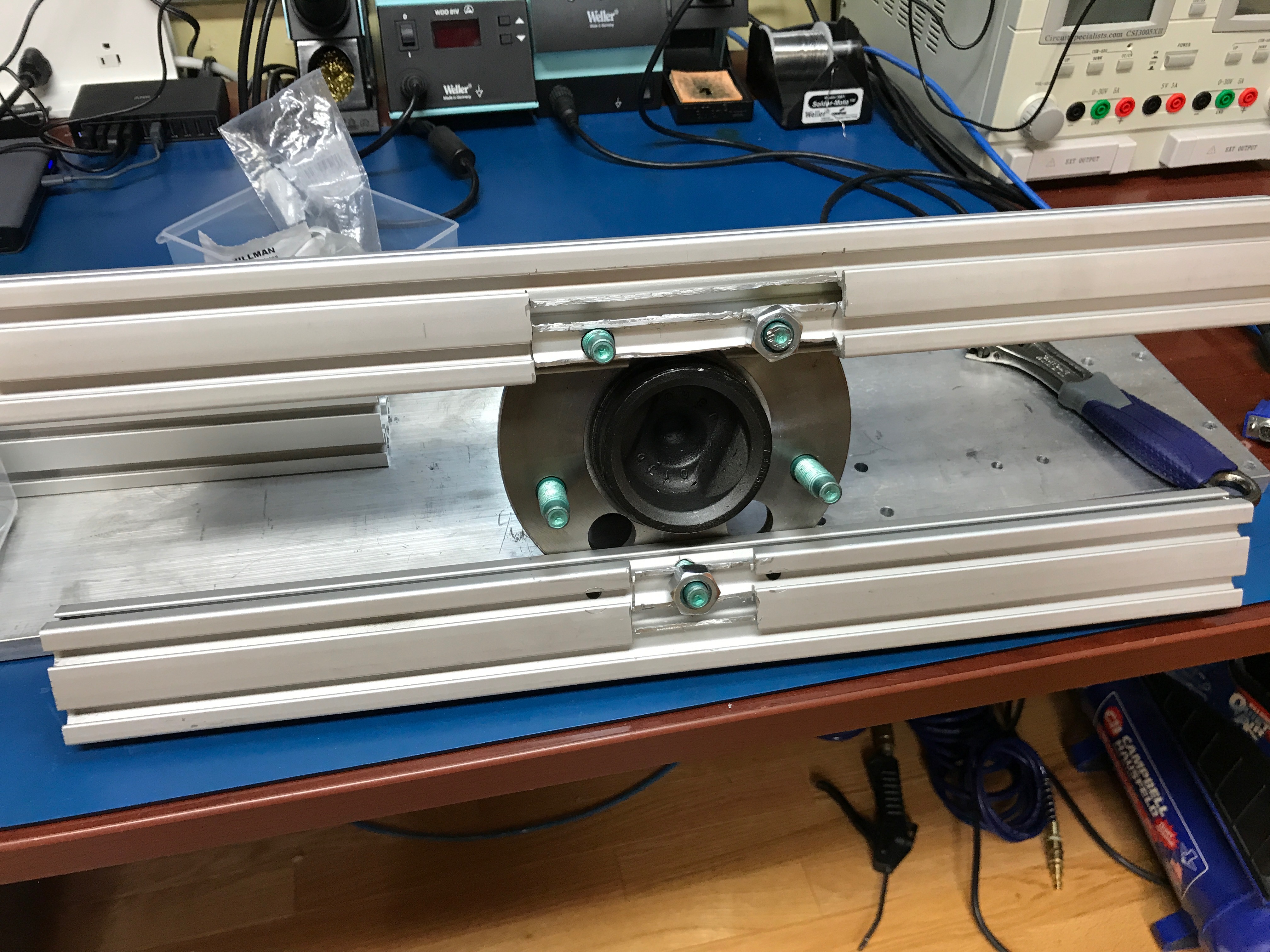\n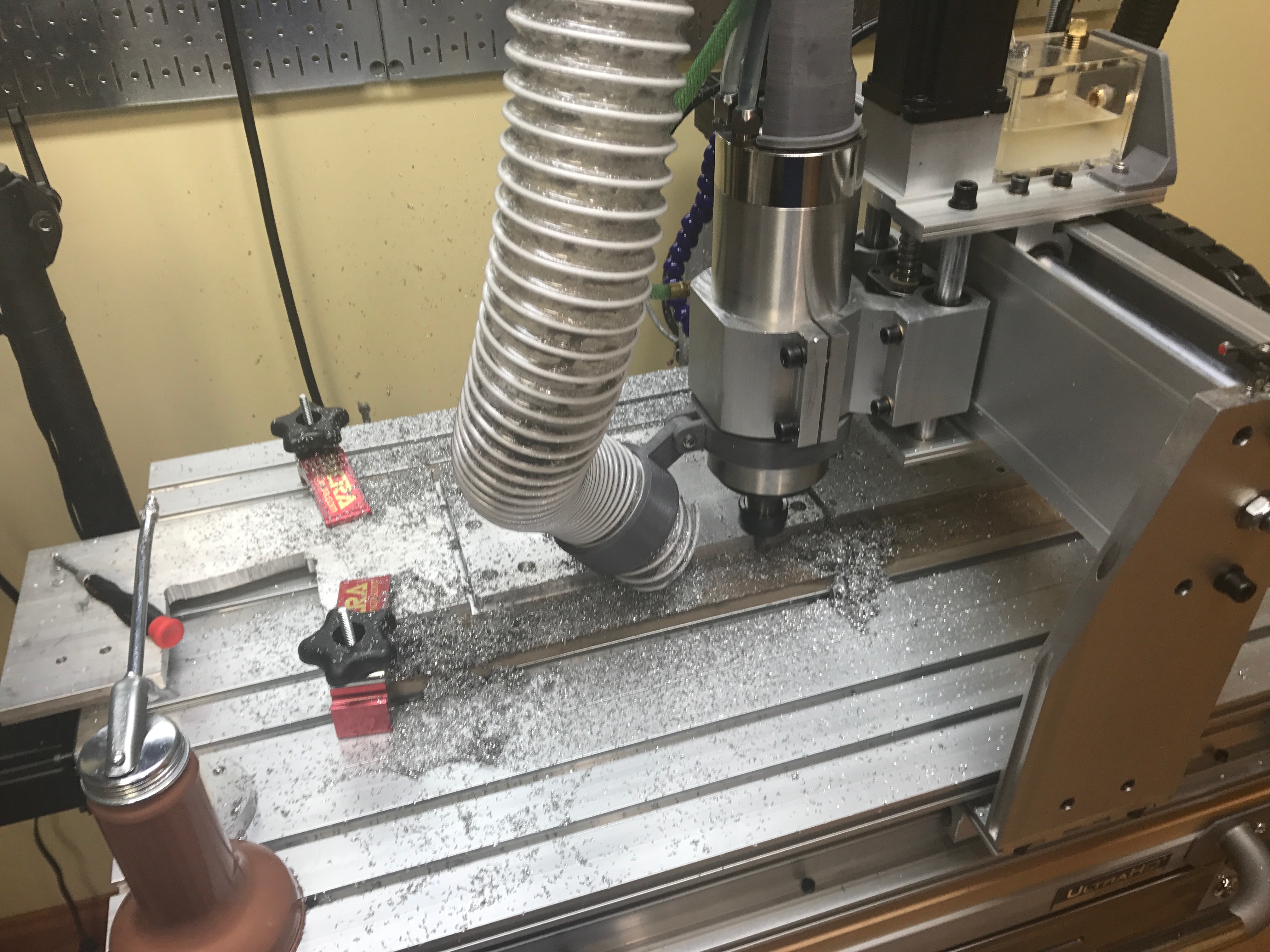\n\nI designed this in Fusion360 and milled it using the CNC that I built.\n\n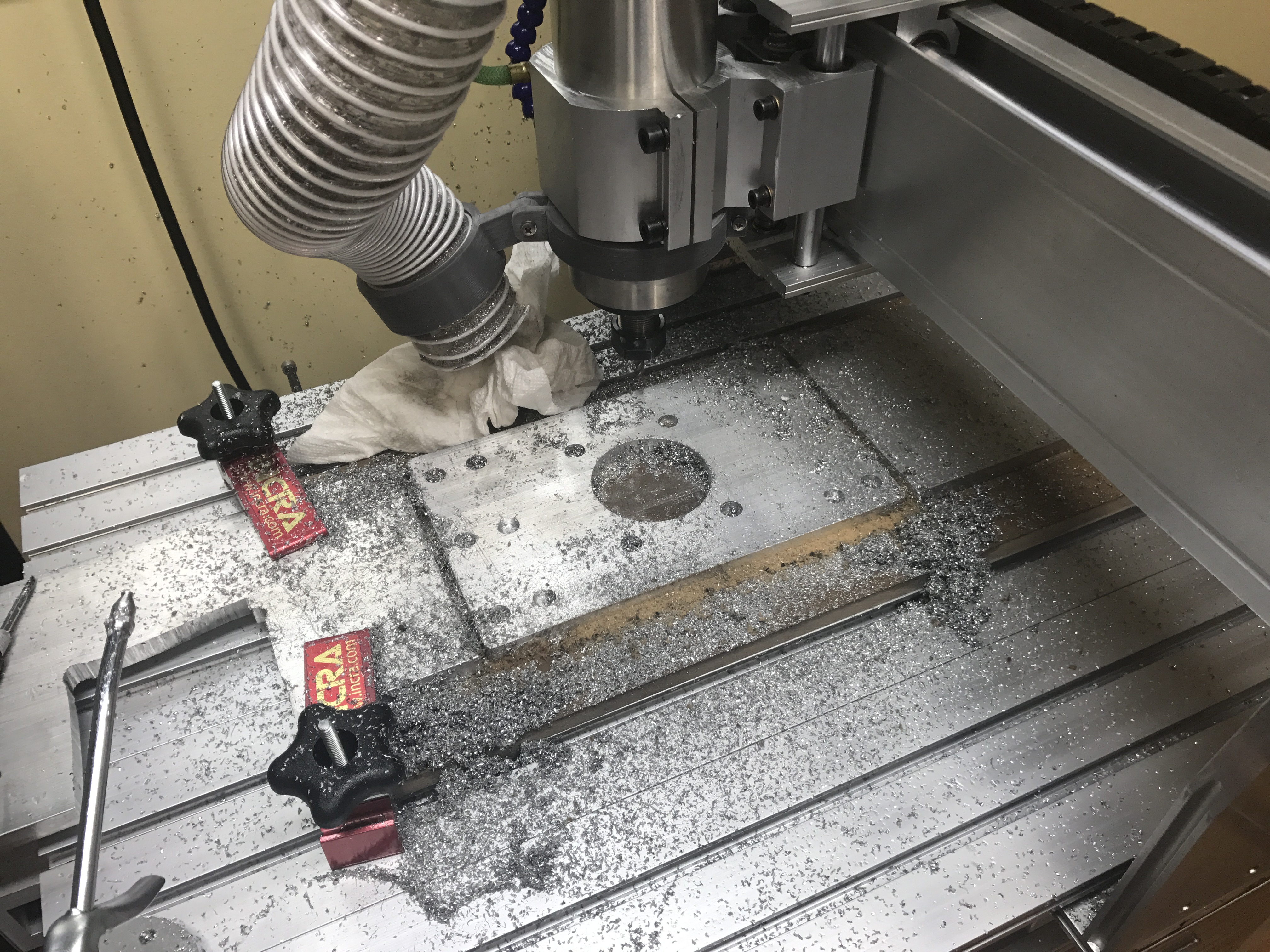\n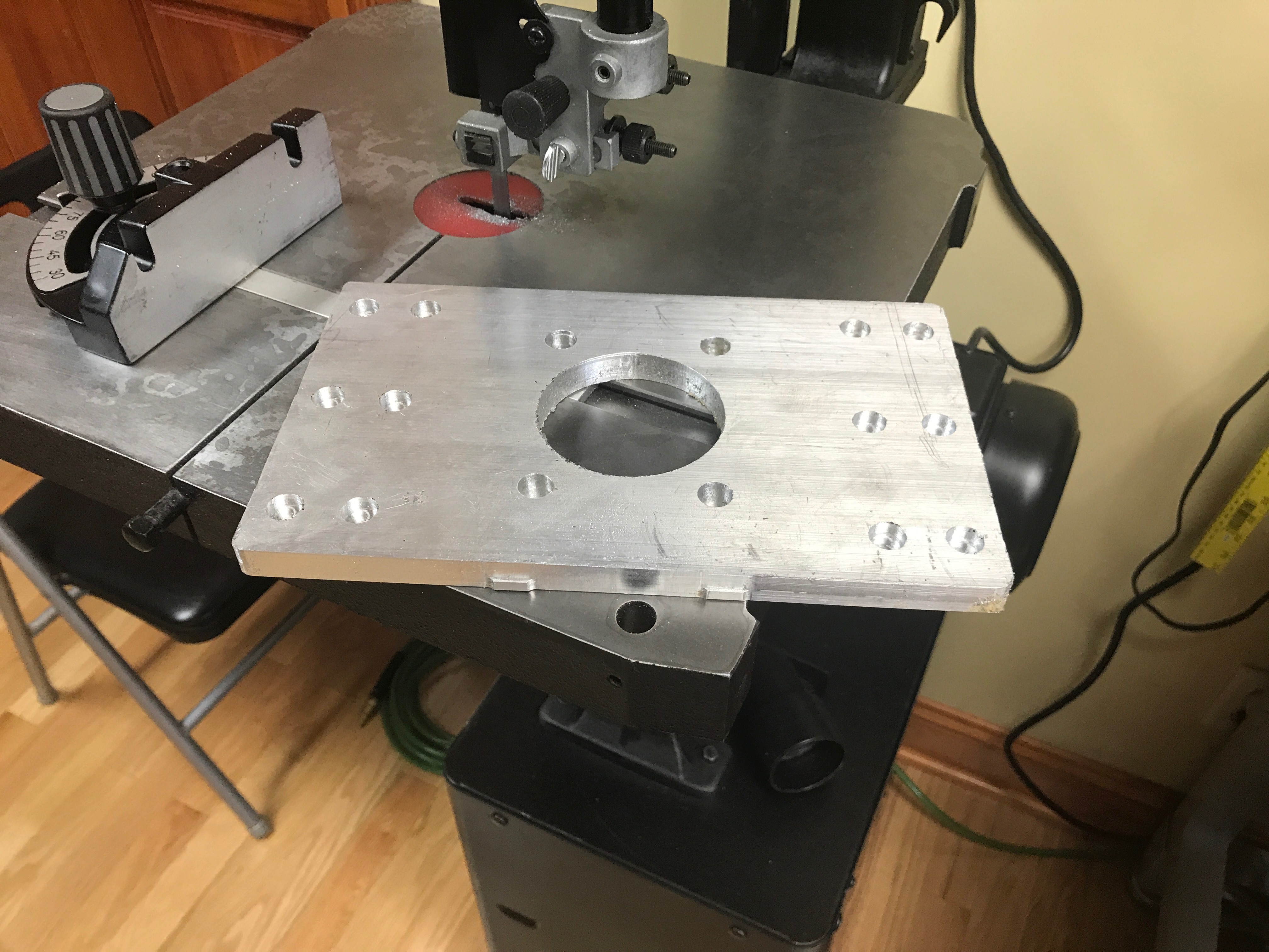\n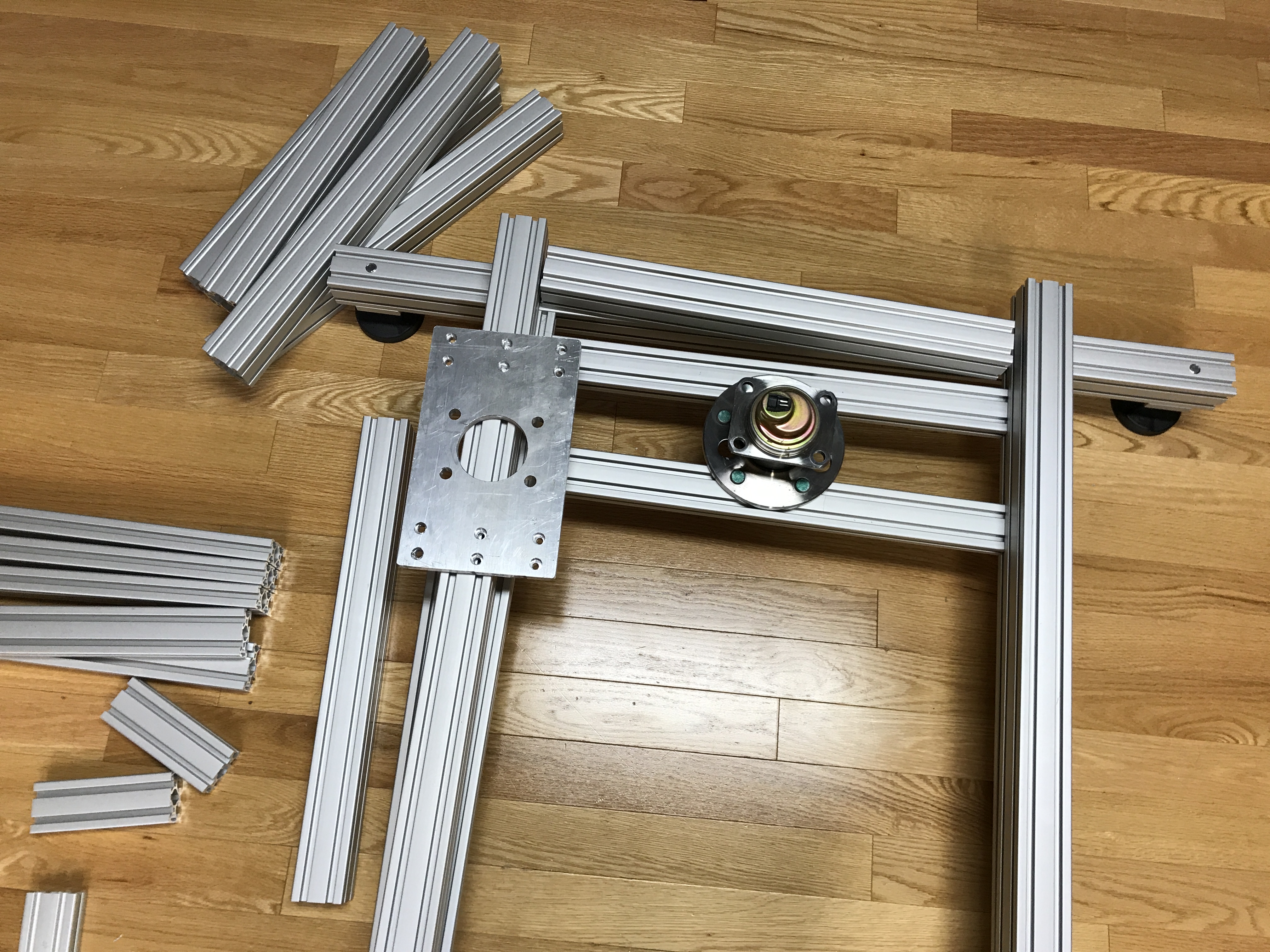\n\nOnce that was done, I was able to thread tap the extrusion for the mid frame and pre-assemble it.\n\n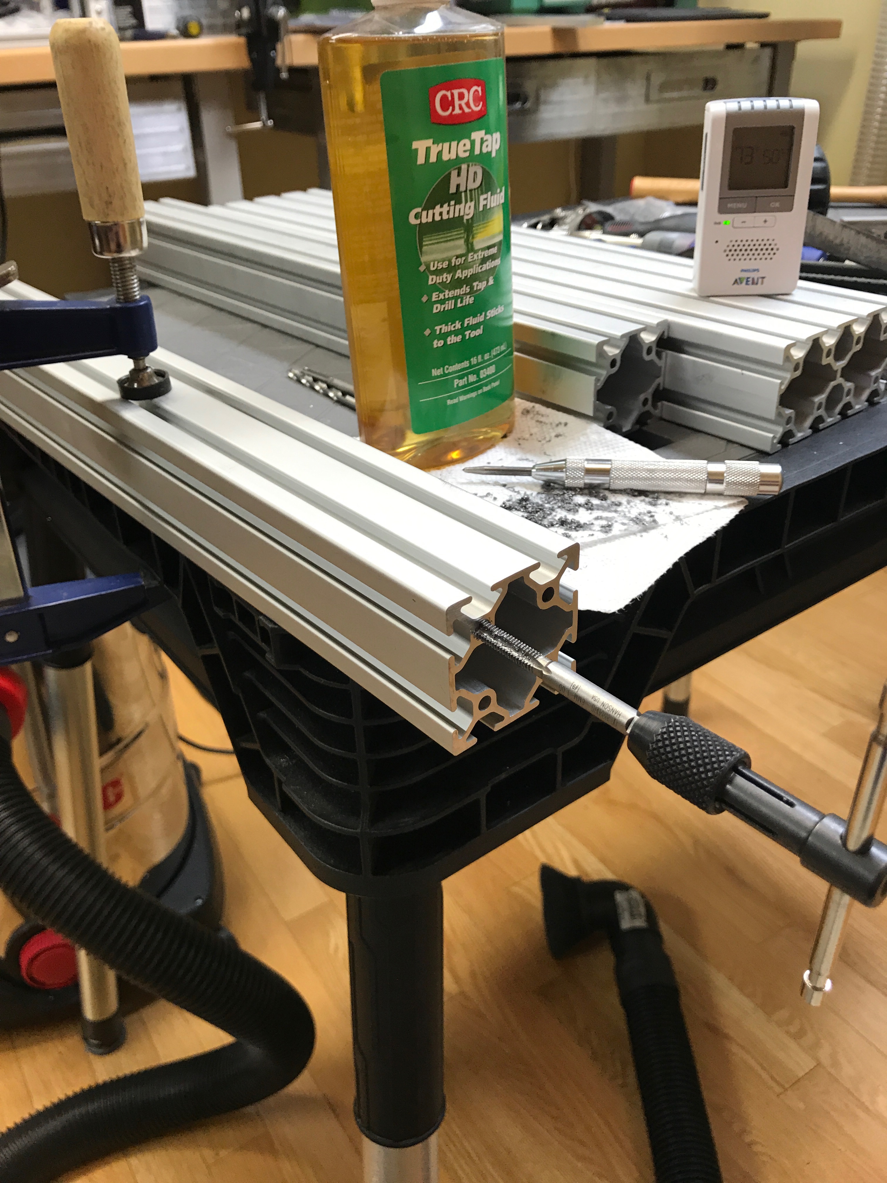\n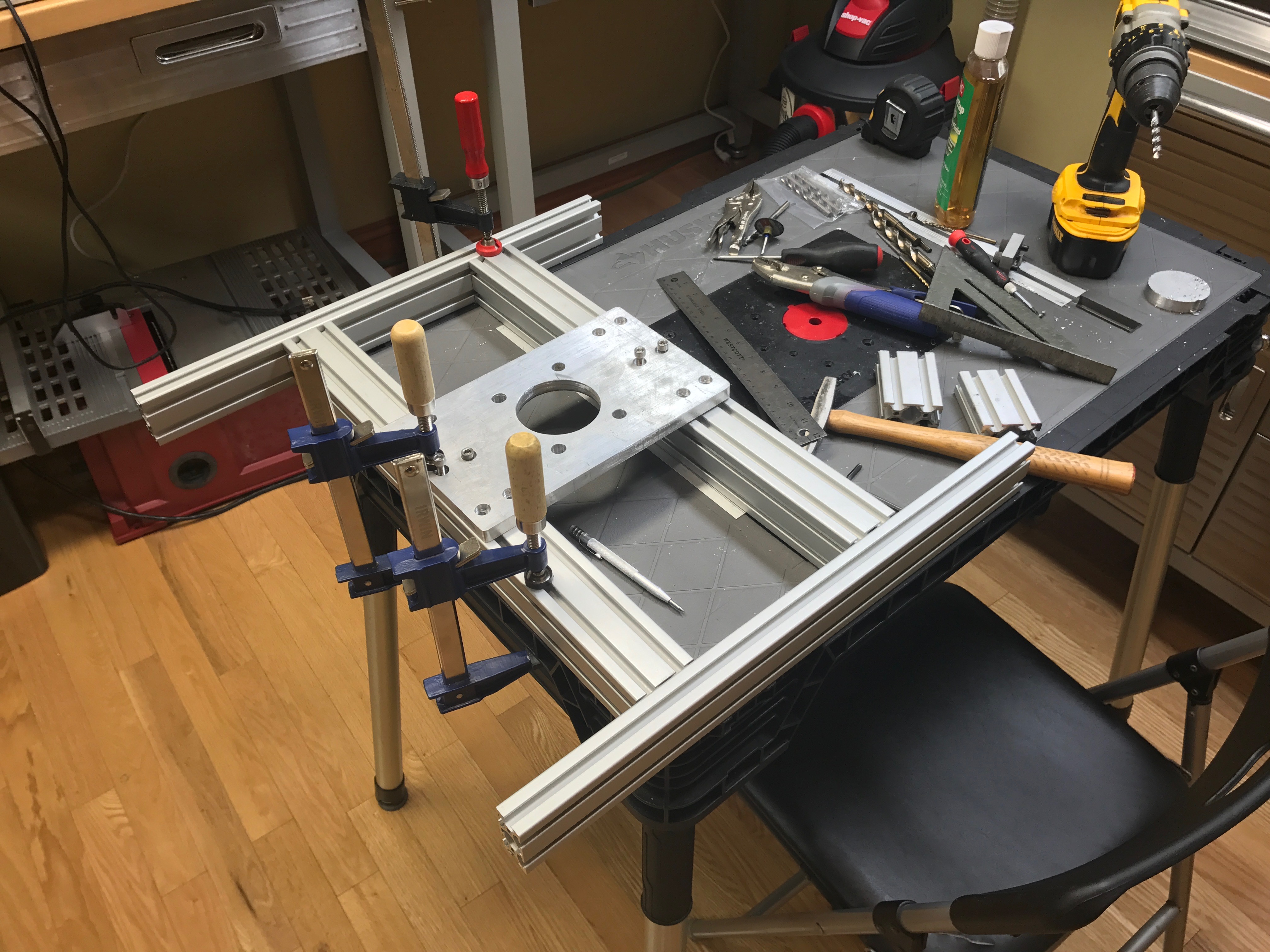\n\nI then attached this section of the mid frame to the lower frame. I used long threaded bolts so that I could adjust the height that the mid frame sat on the lower frame.\n\n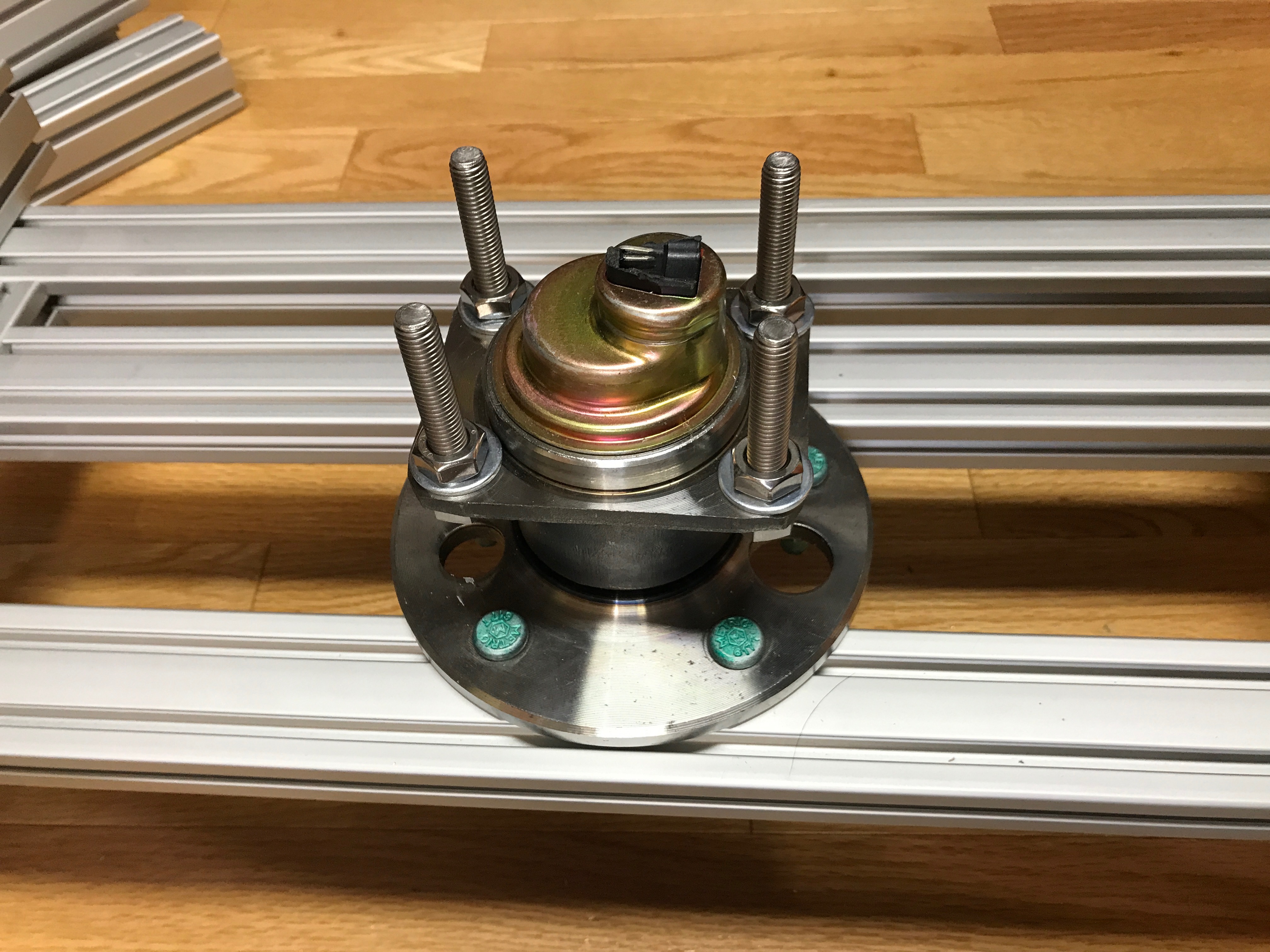\n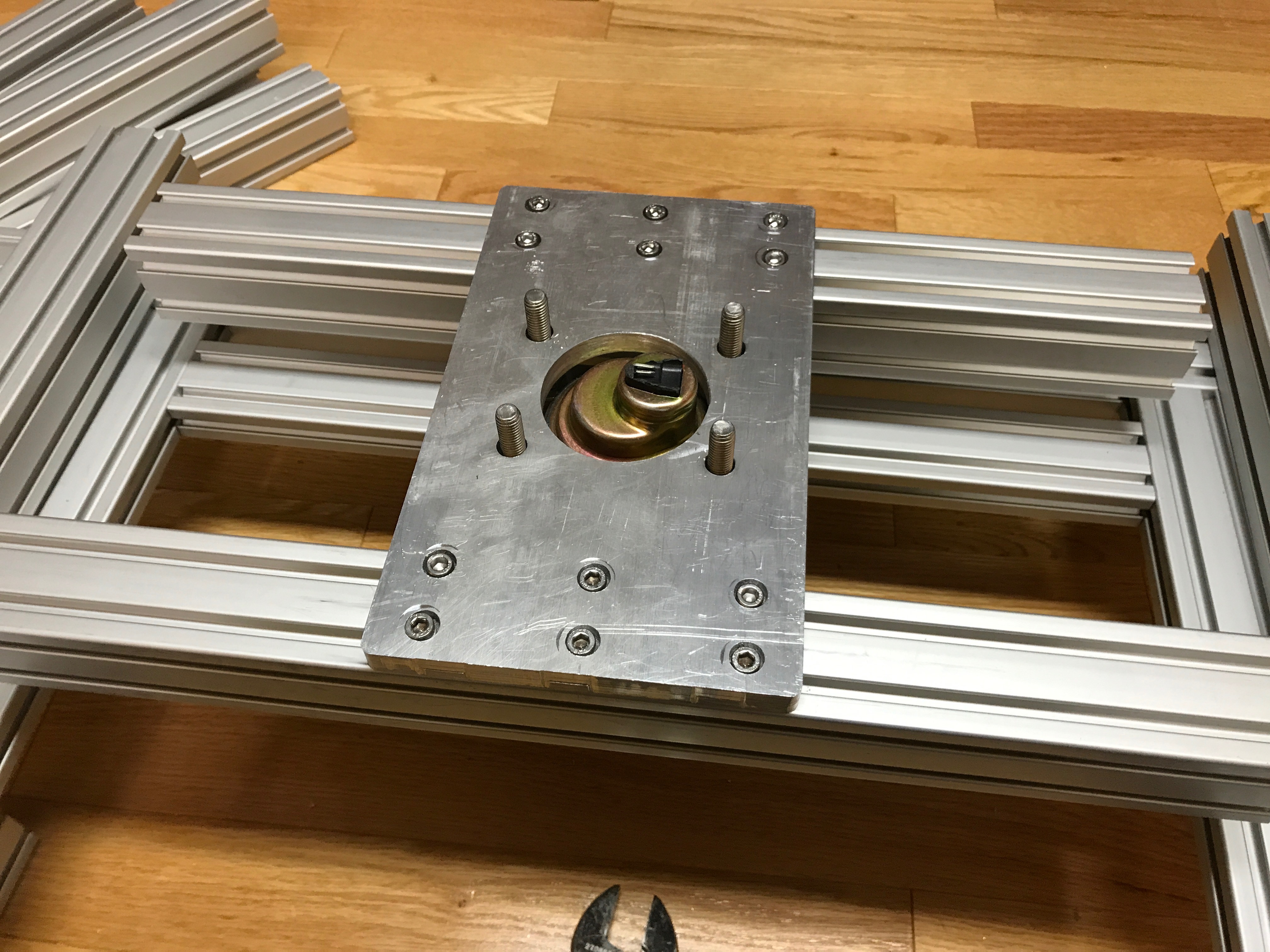\n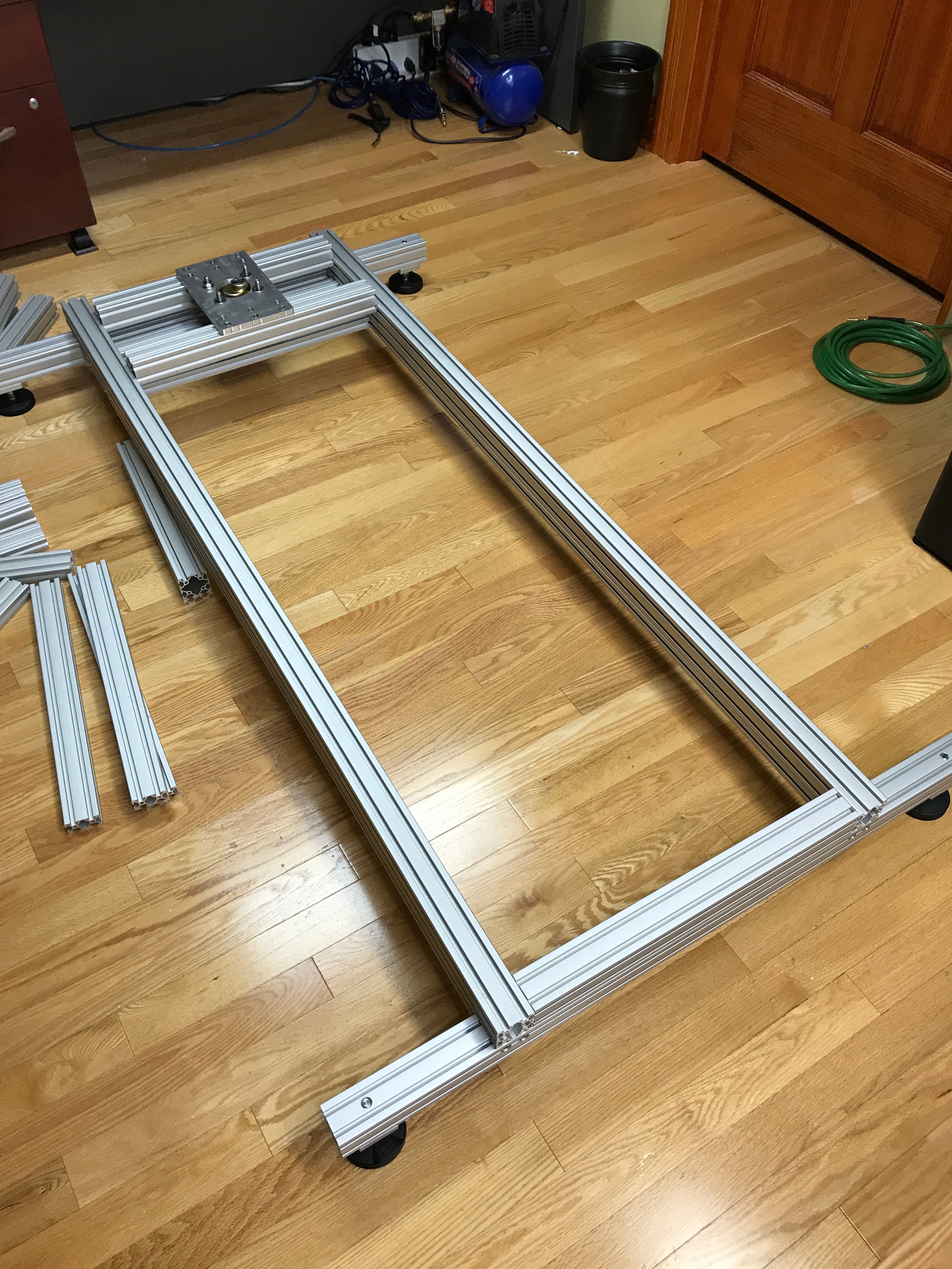\n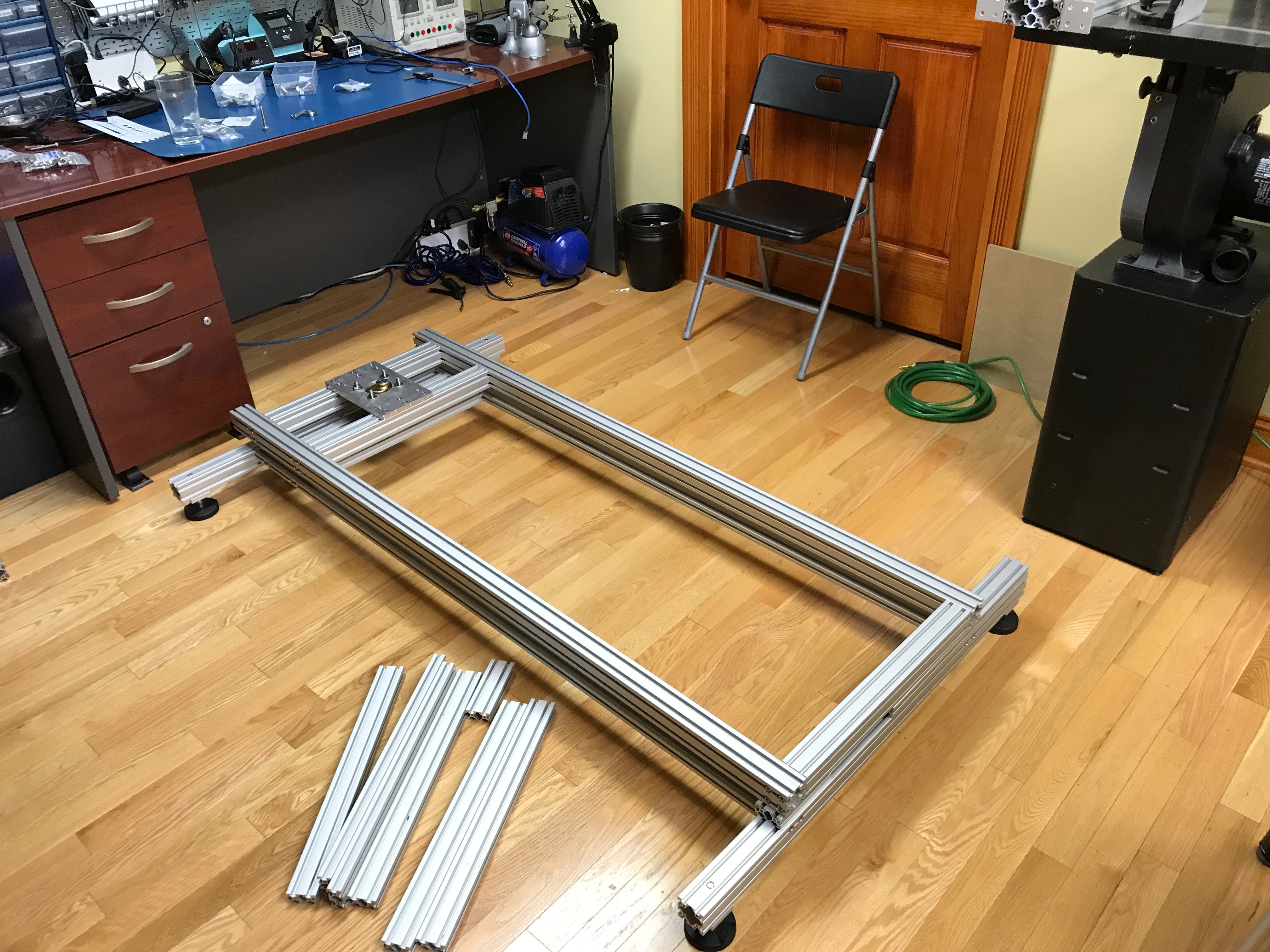\n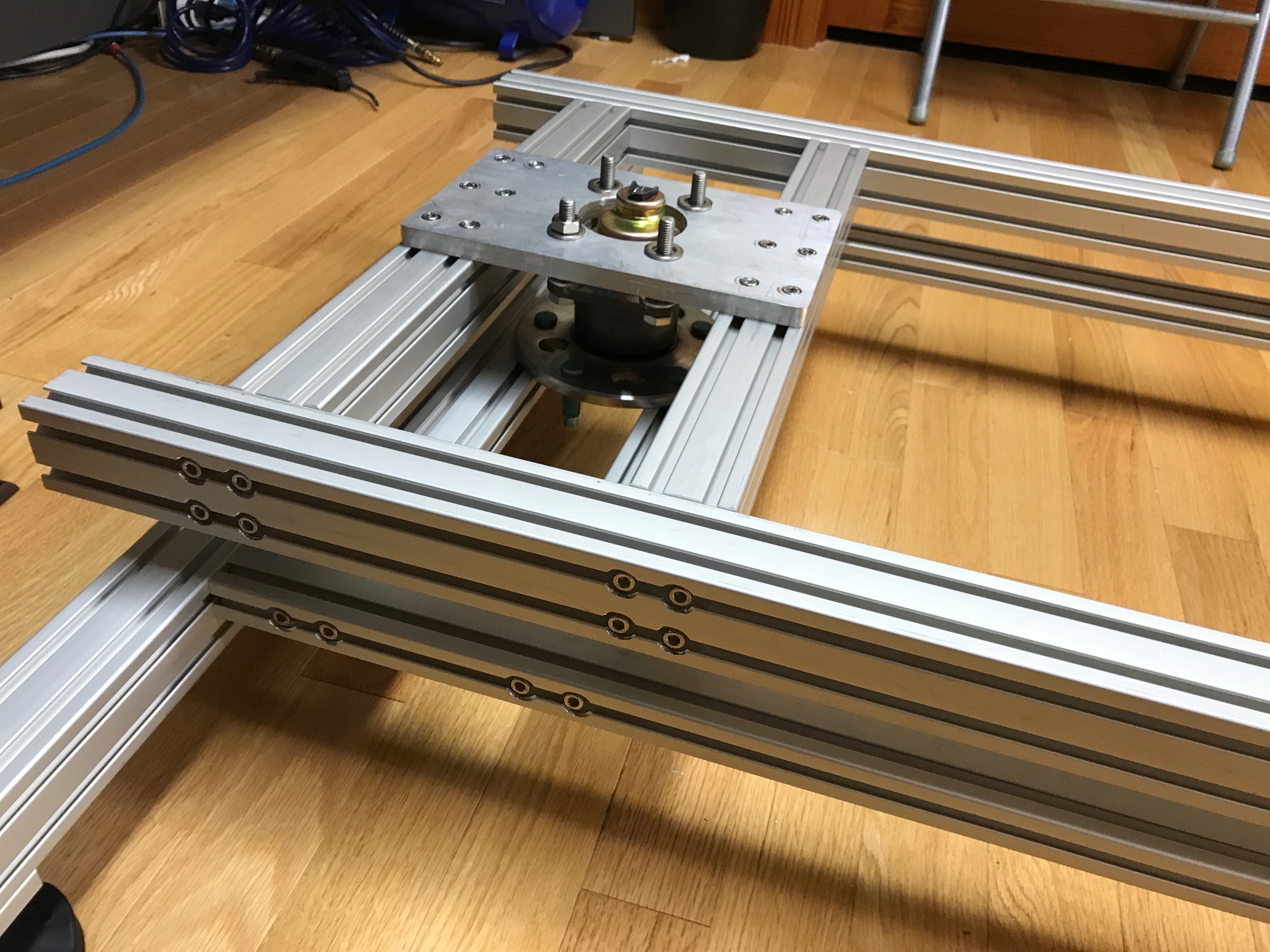\n\nThe top frame was then mocked up. The top frame sits on linear sliders to allow it to slide back and forward. This was the biggest improvement over version 1.\n\n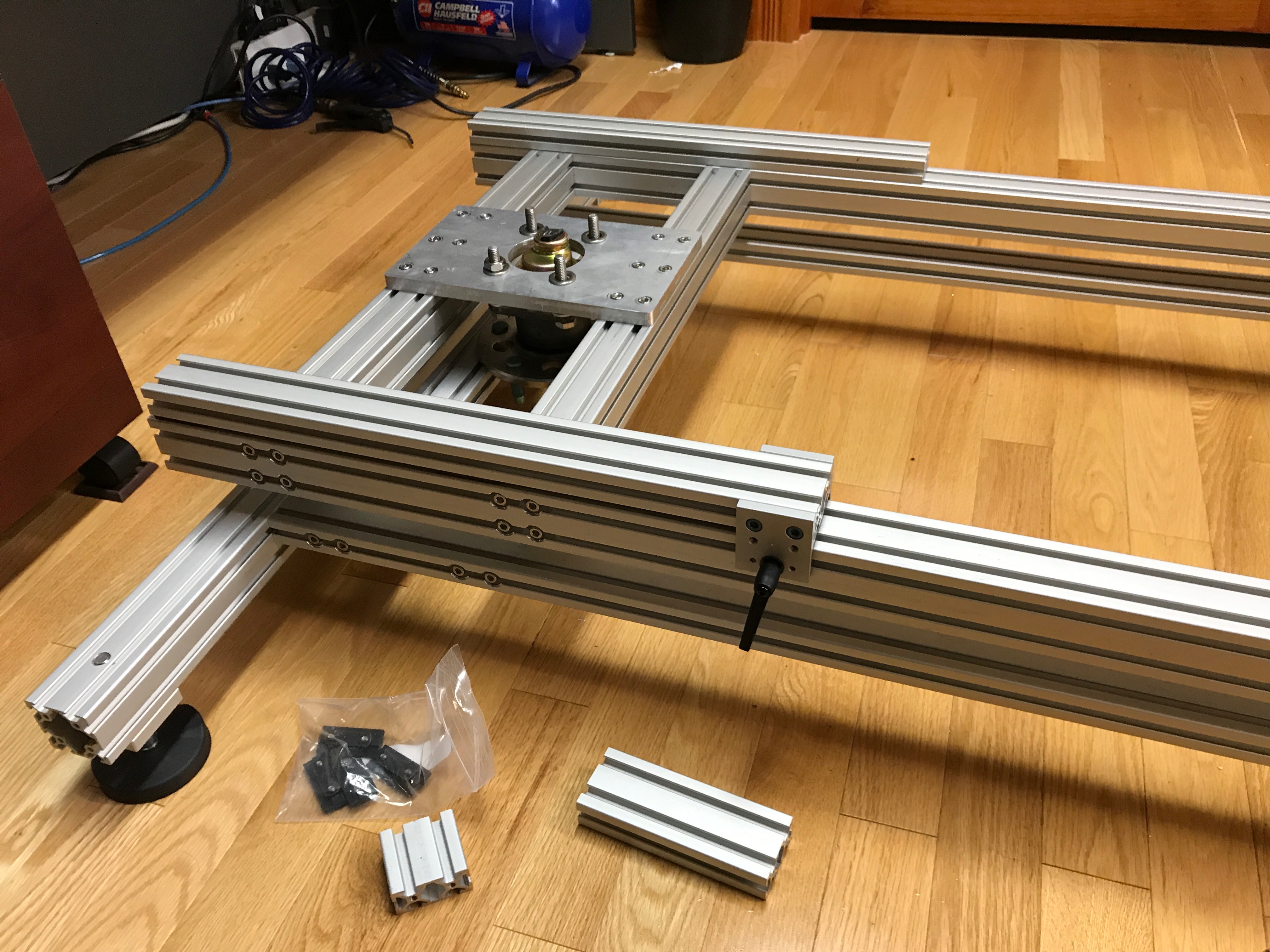\n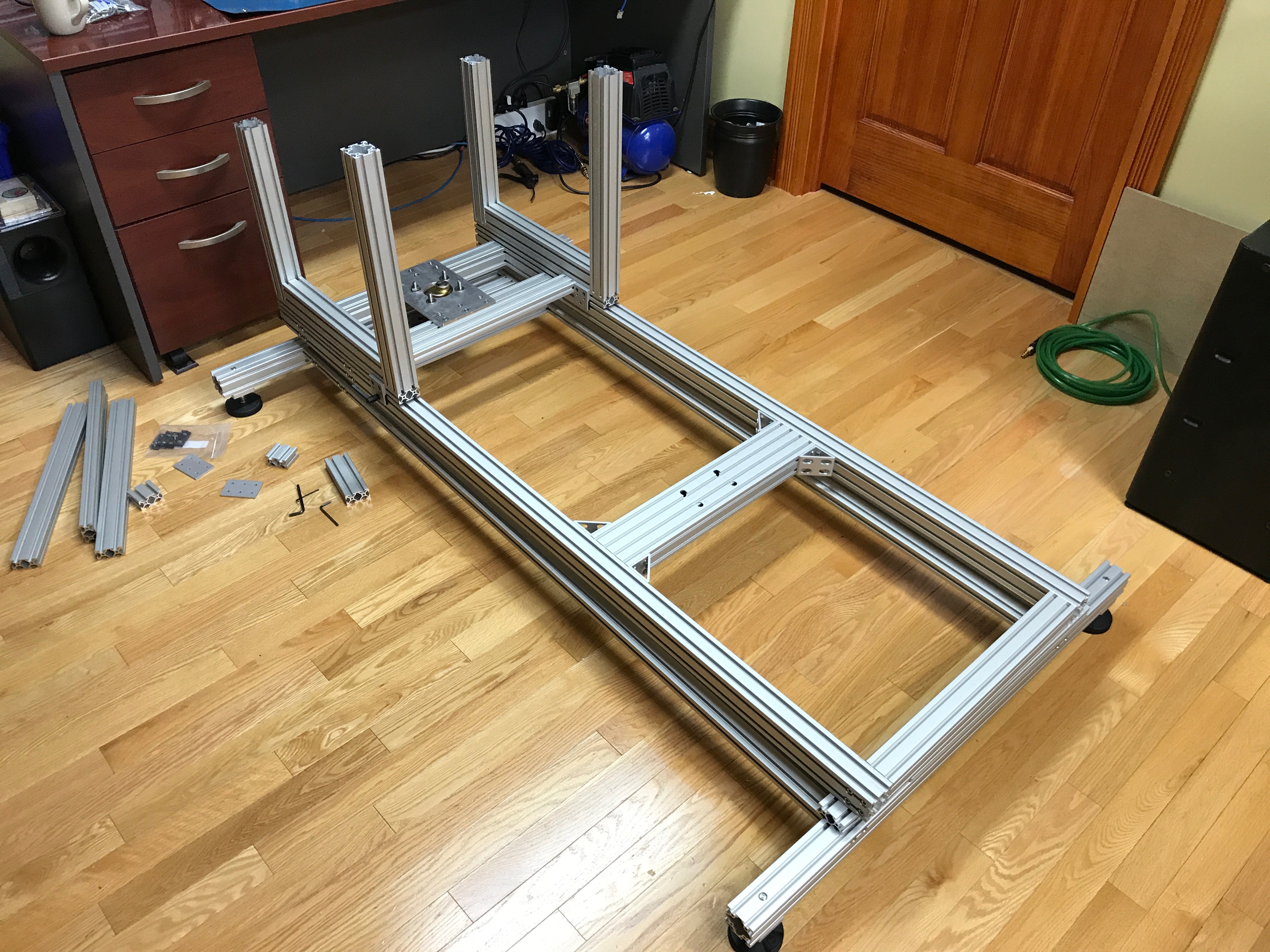\n\nThere was a lot of drilling and thread tapping to get all the pieces of the top frame together.\n\n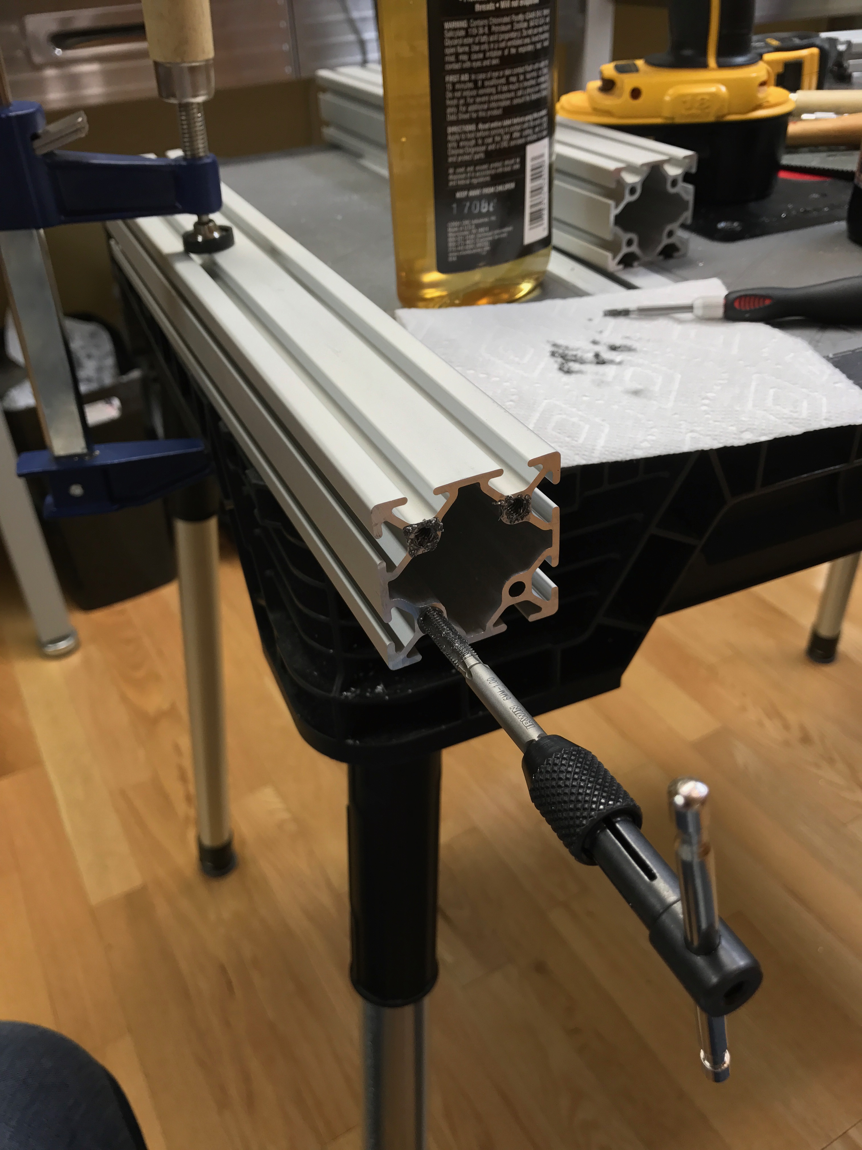\n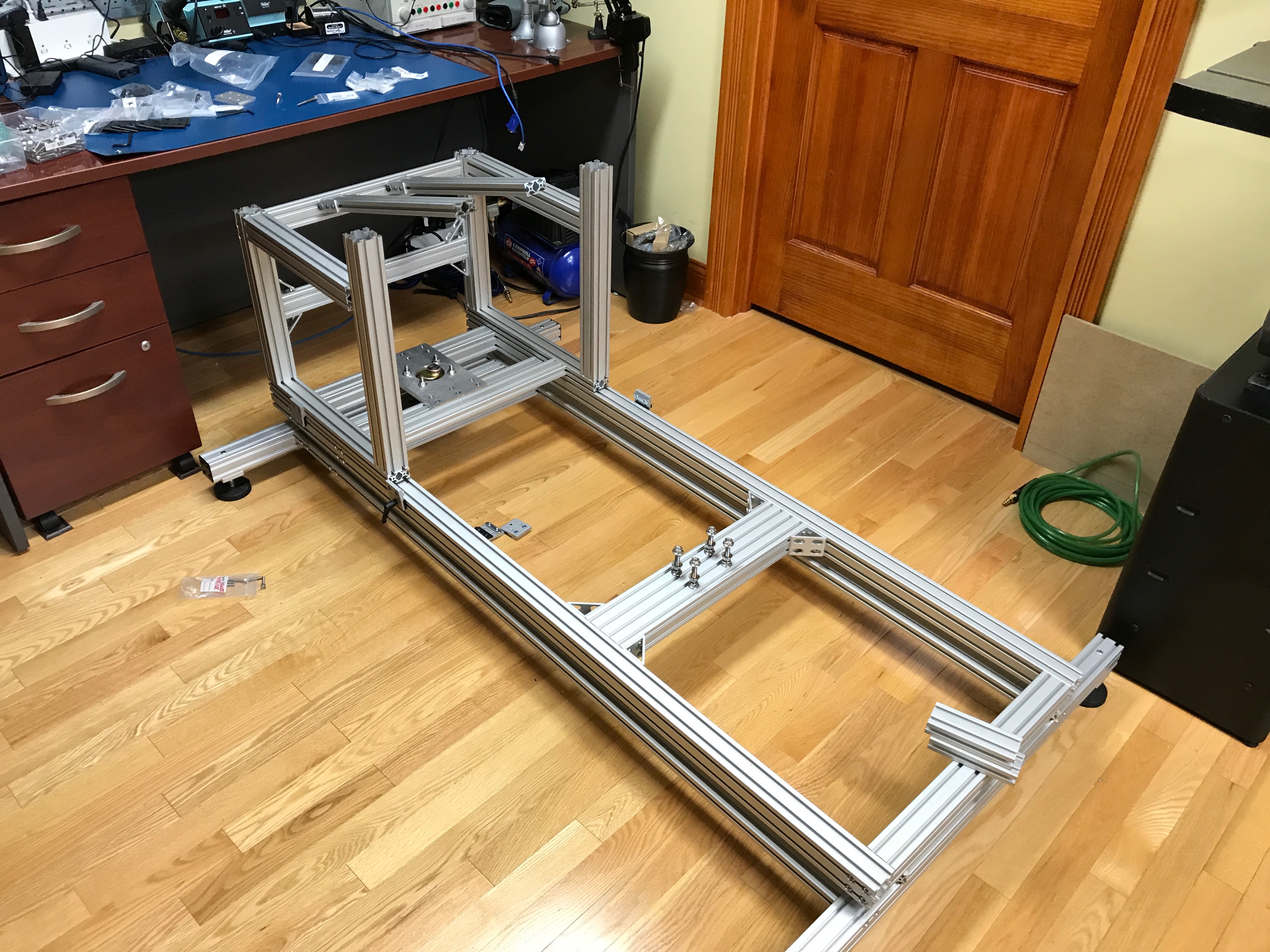\n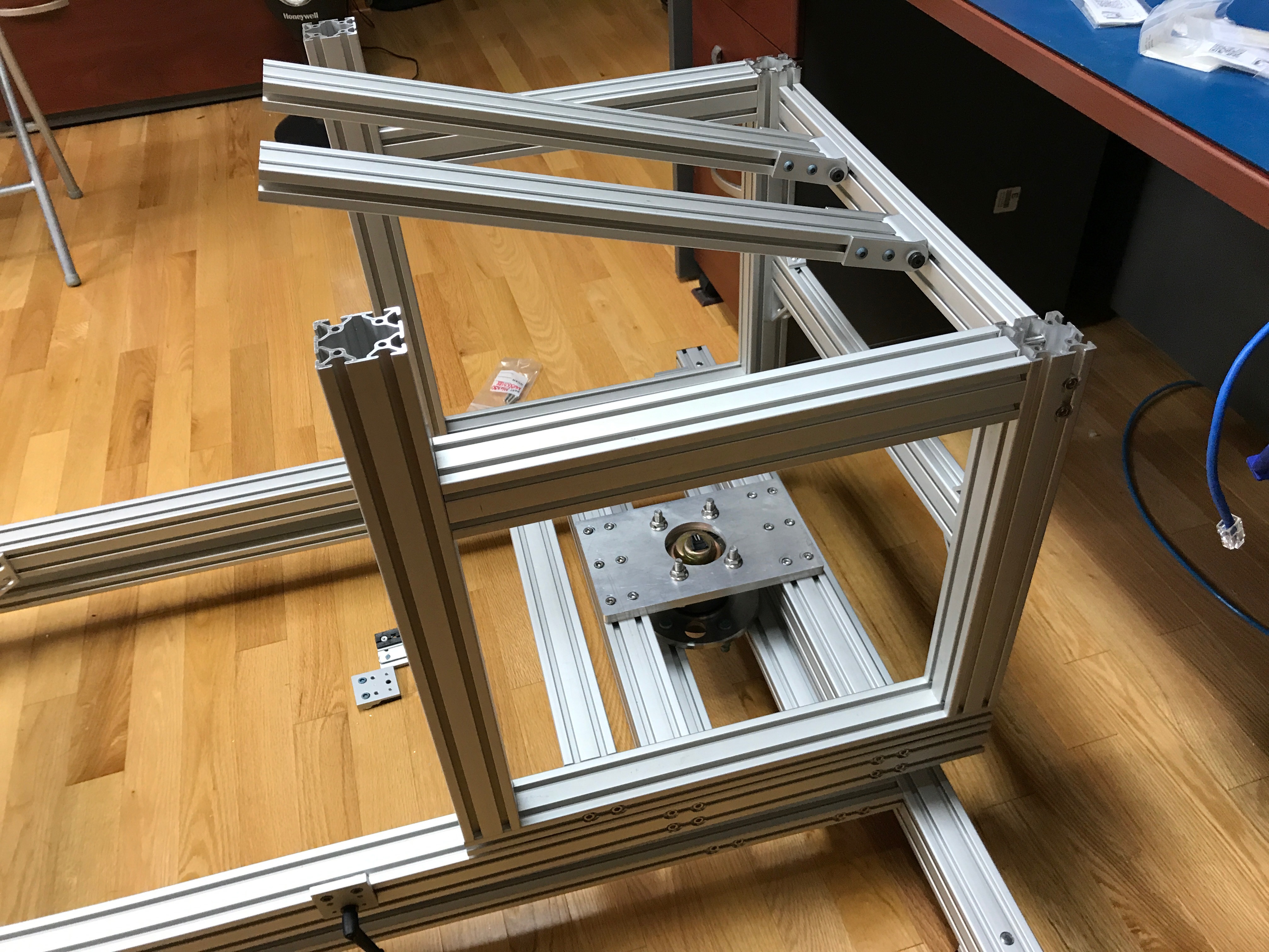\n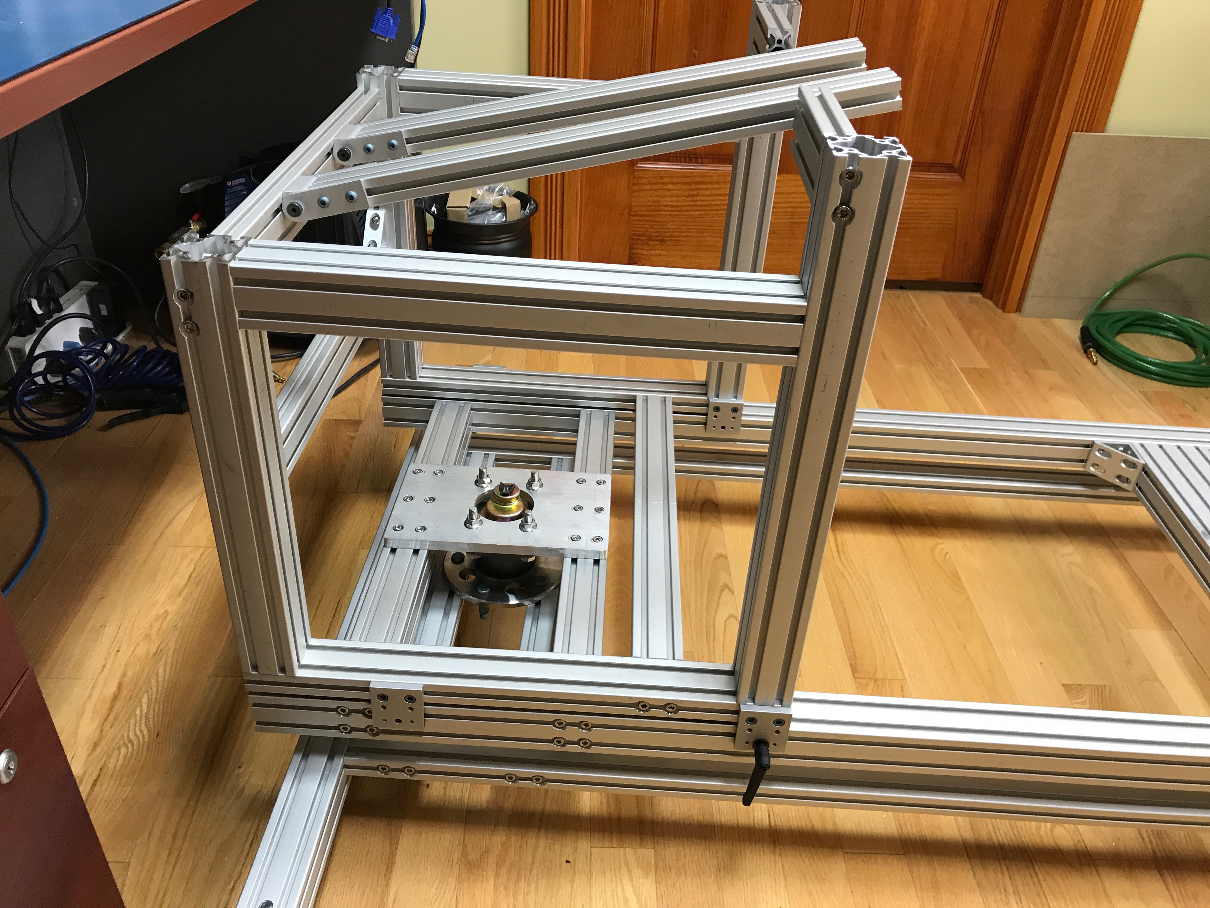\n\nI pieced together a seat mount using 80/20, rather than using the SimXperience DIY seat kit that I had for version 1. I did this so that I could get the seat sitting lower in the frame.\n\n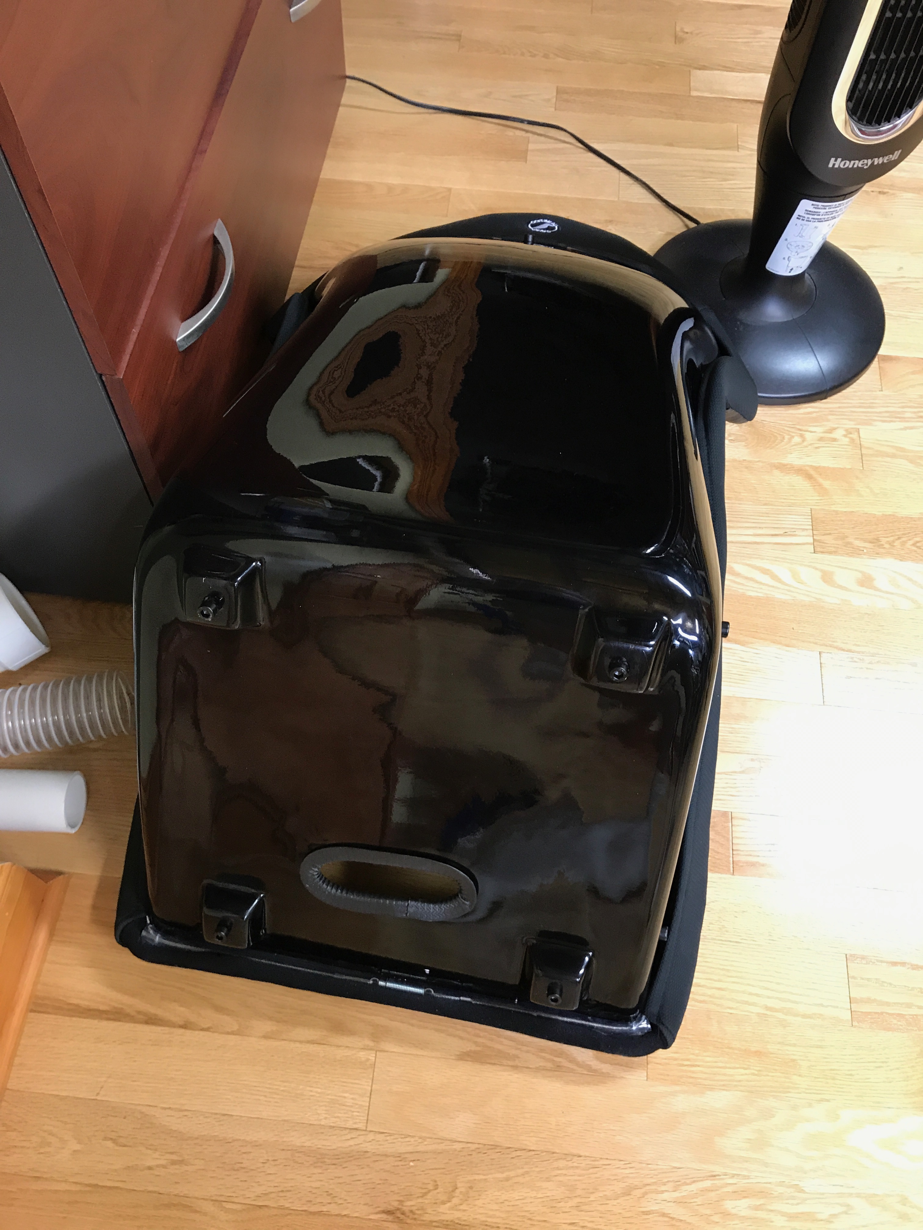\n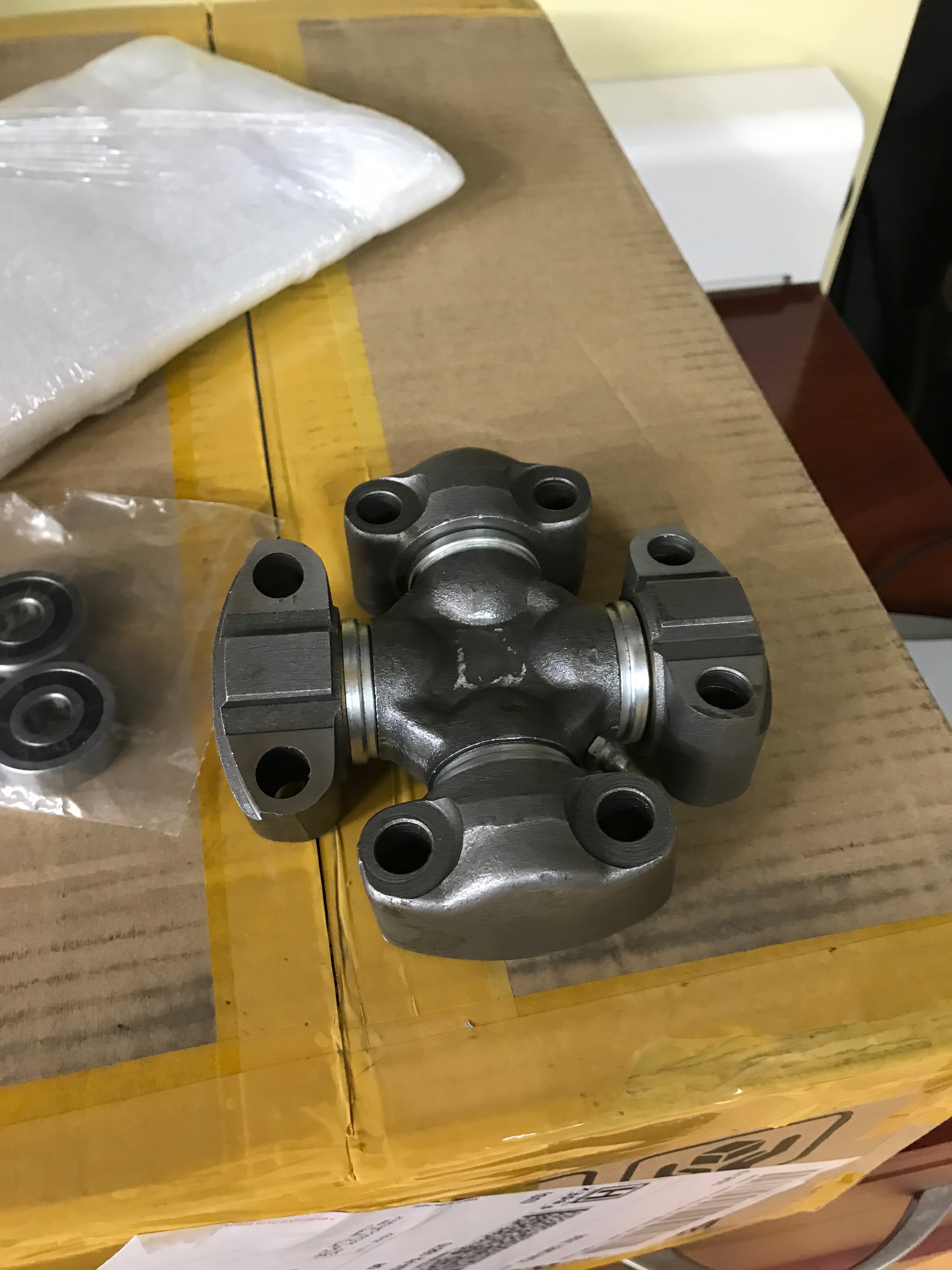\n\nI found a great universal joint on eBay for $30. With this wing style U-Joint, I had a lot more flexibility with how I mounted things. I had to make a quick and dirty jig to get the hole spacing correct as the holes ended up being right along the edge of an extrusion.\n\n\n\n\n\nI also had to notch out part of the extrusion on the mid frame to allow the U-Joint bolts to sit down further at the extreme angles.\n\n\n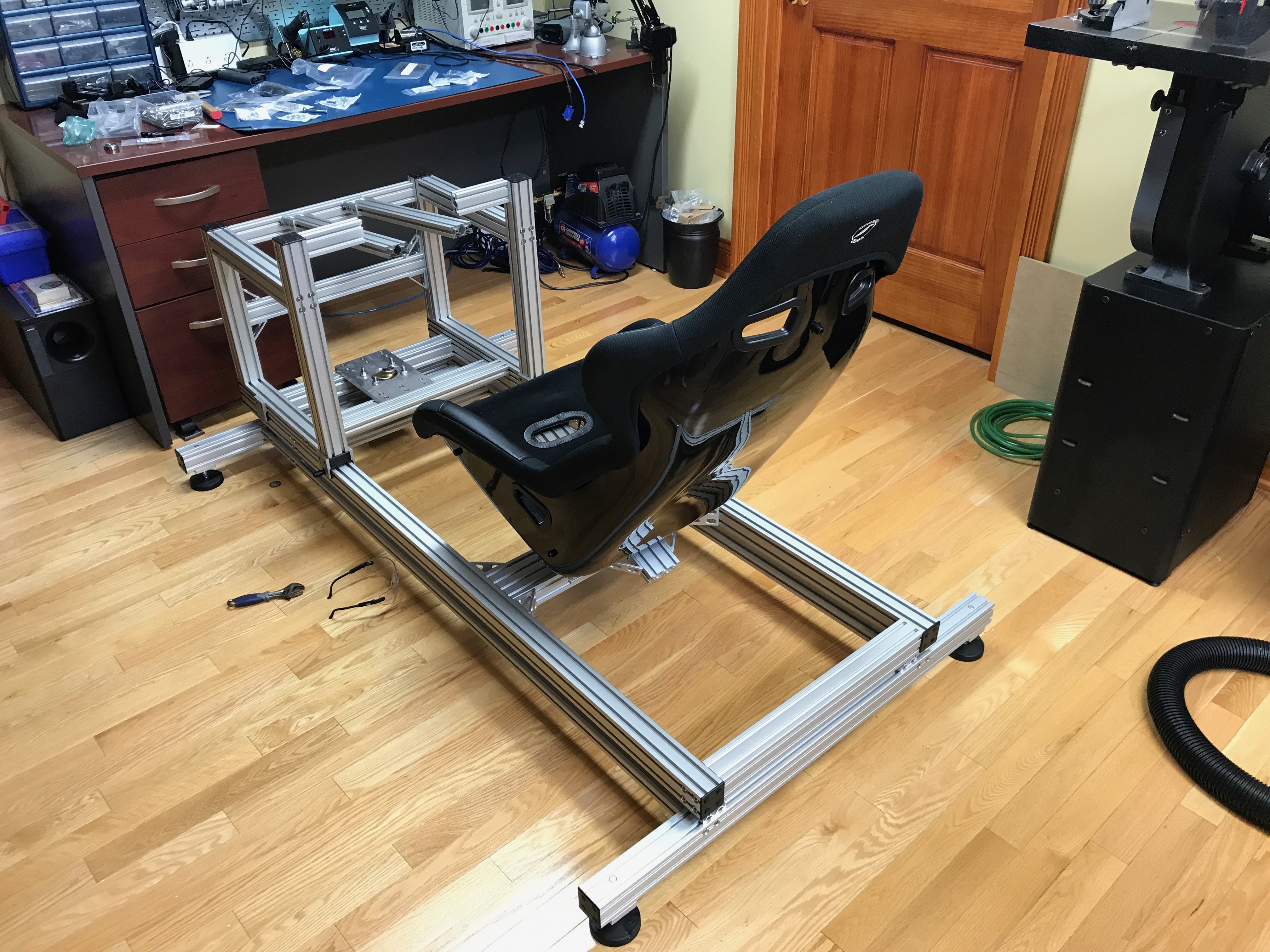\n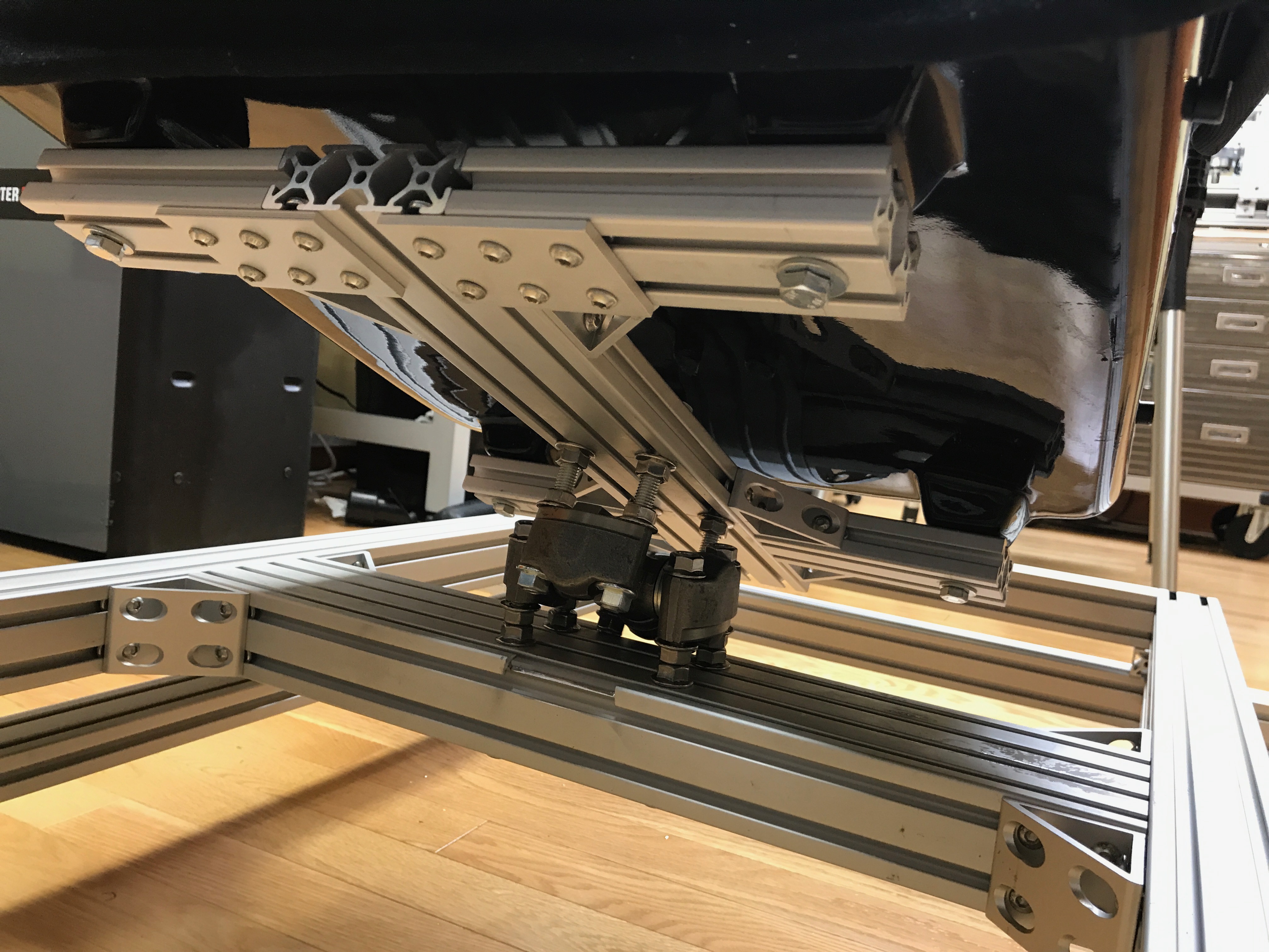\n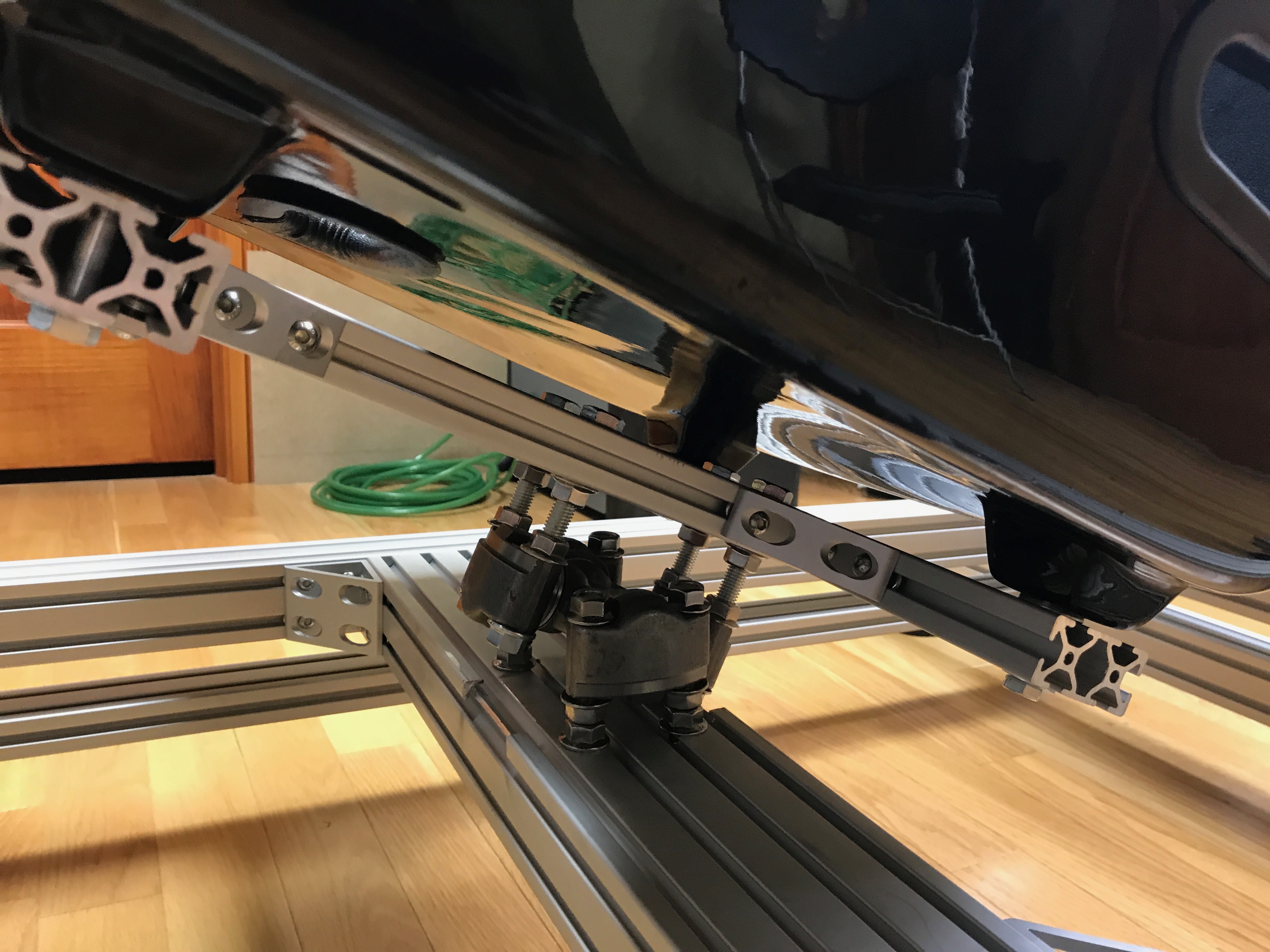\n\nWith the seat mounted, I then focused on the rear rollers for the traction loss mechanism. These rollers ultimately set the height of the mid frame from the lower frame. I designed the brackets in Fusion360 and milled them on my CNC.\n\n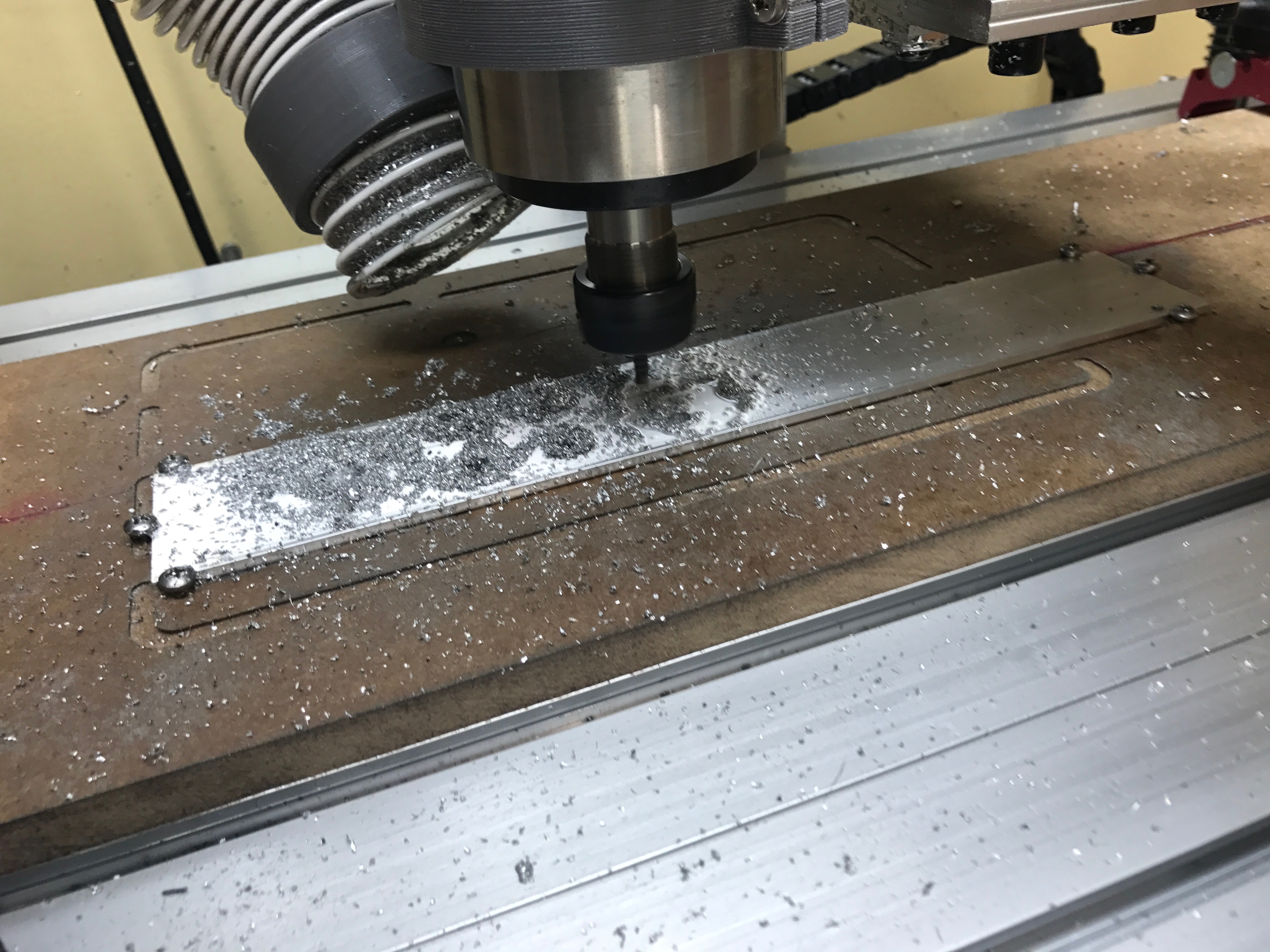\n\nI used track rollers that I found on eBay. They were called LR200NPPU Track Roller Double Row Bearing Sealed 10x32x9 Track Bearings 18165. I got 4 for $20.\n\n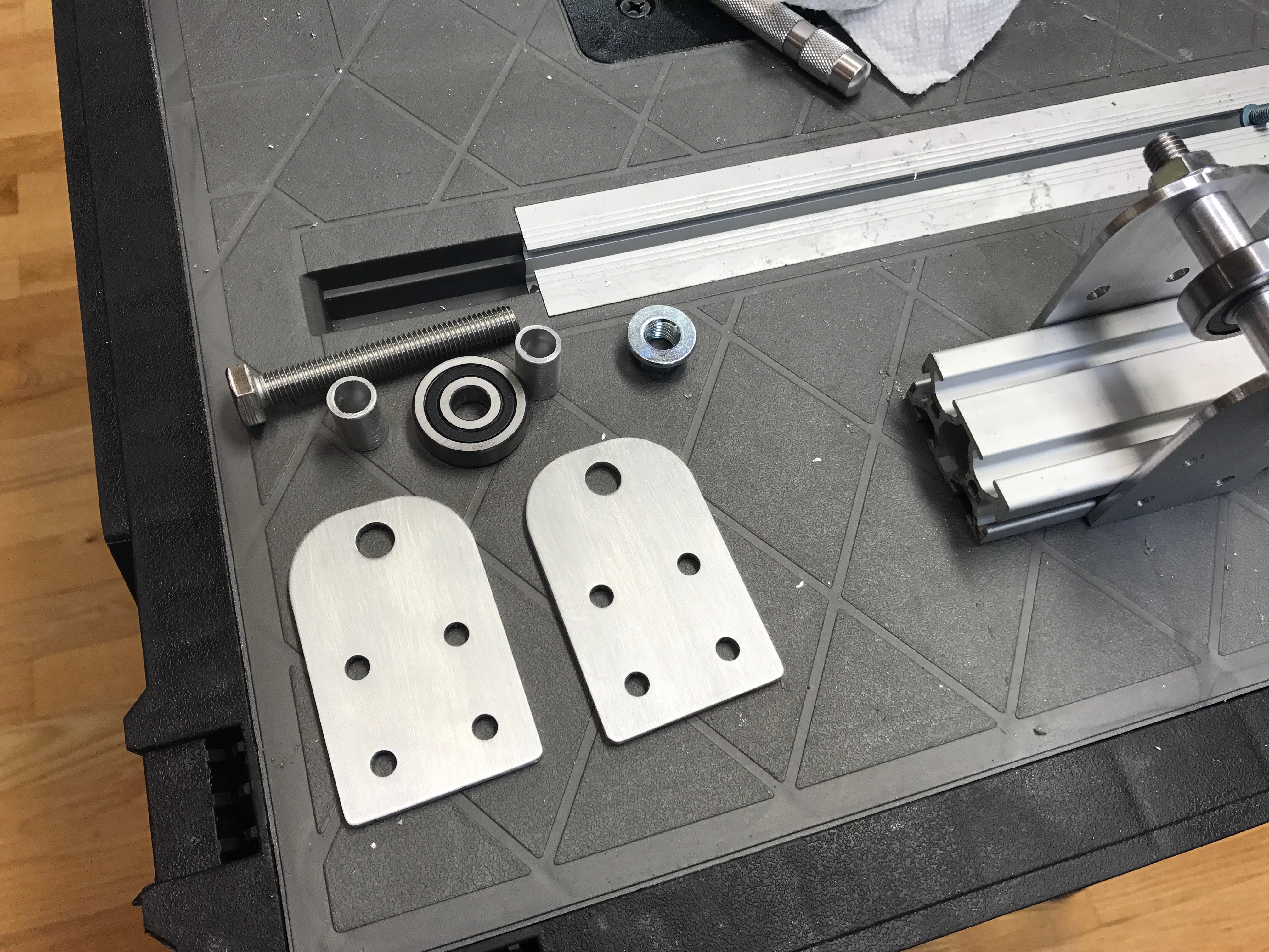\n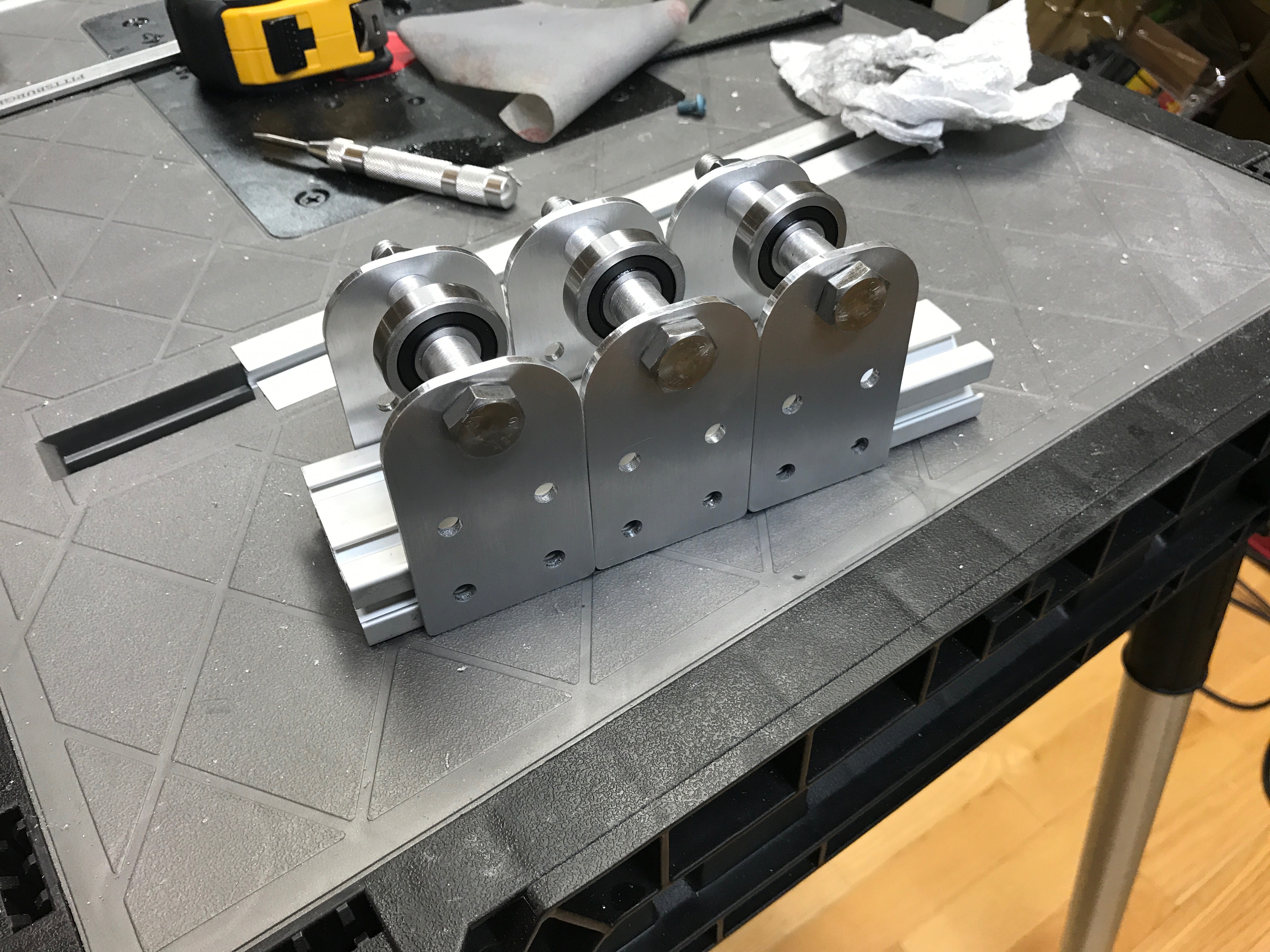\n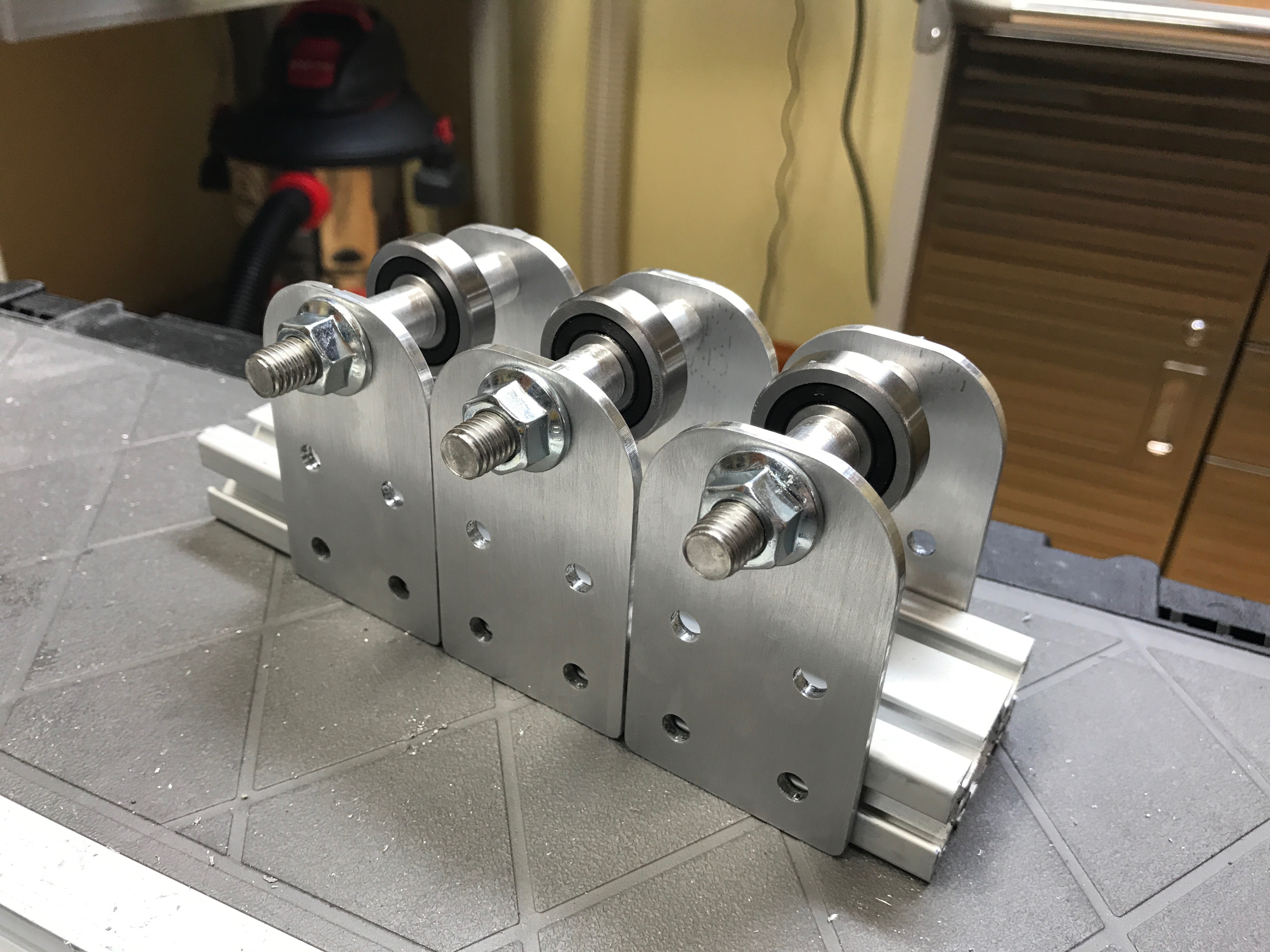\n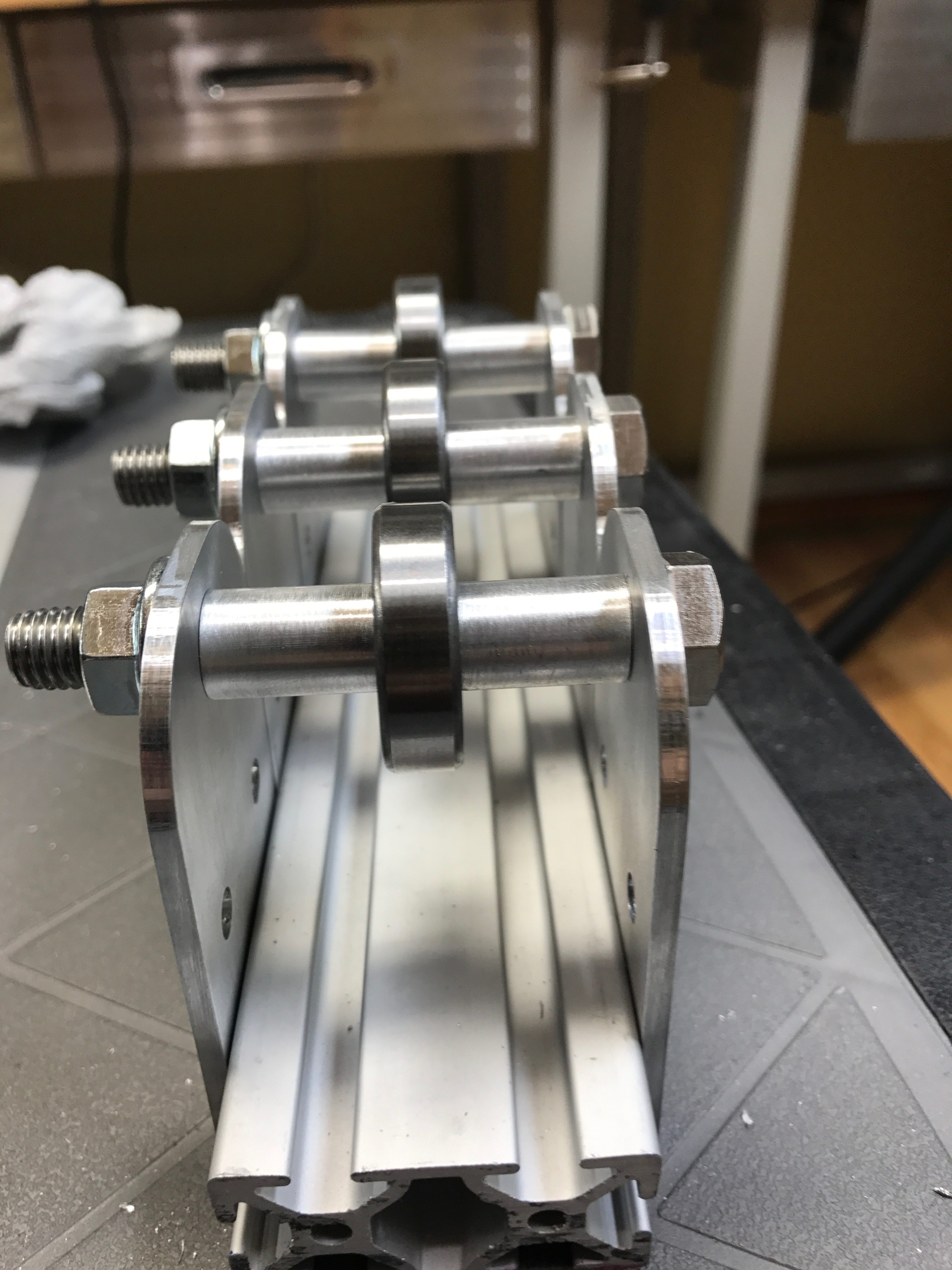\n\nI then mounted them on the cross member of the mid frame.\n\n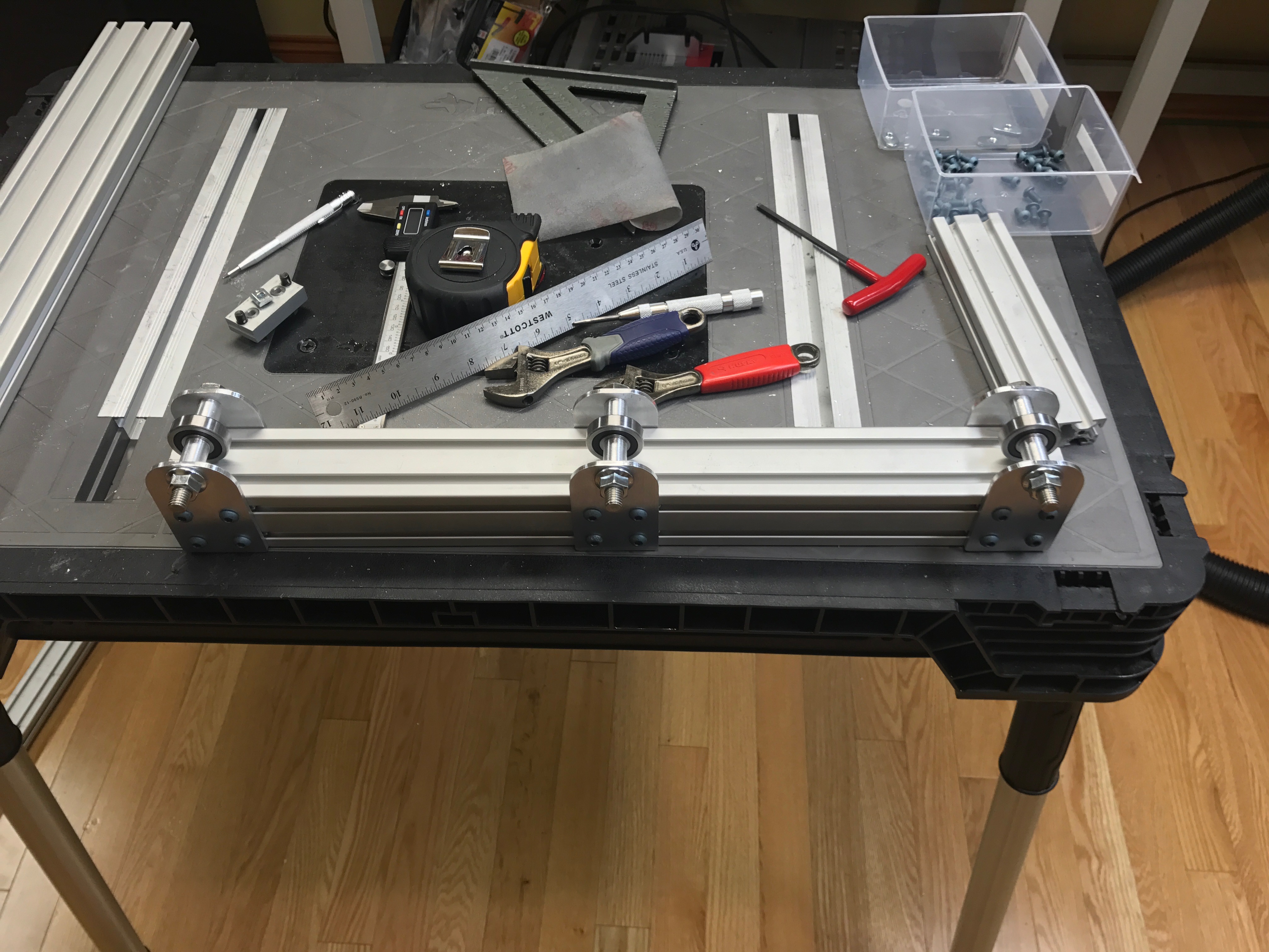\n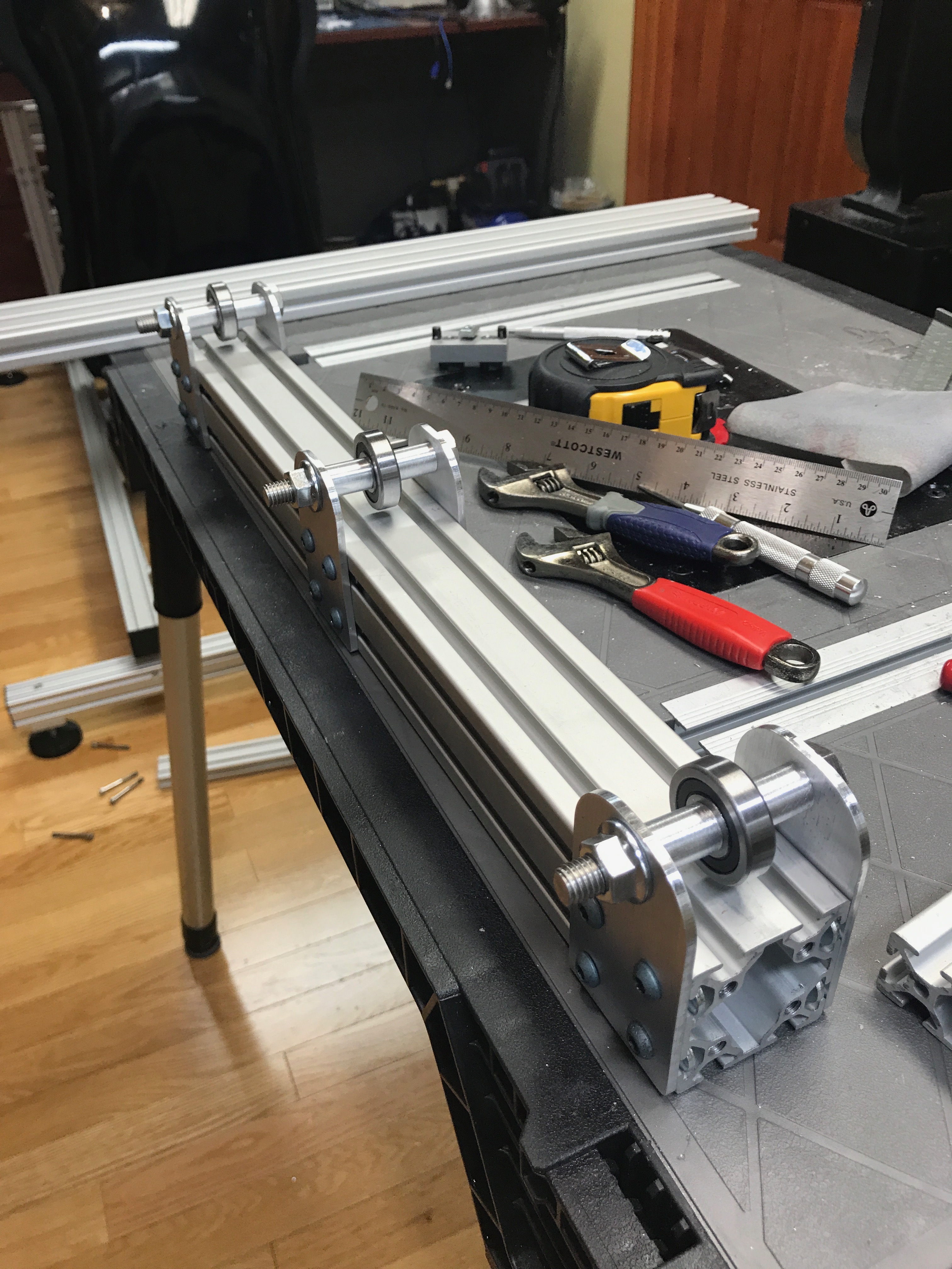\n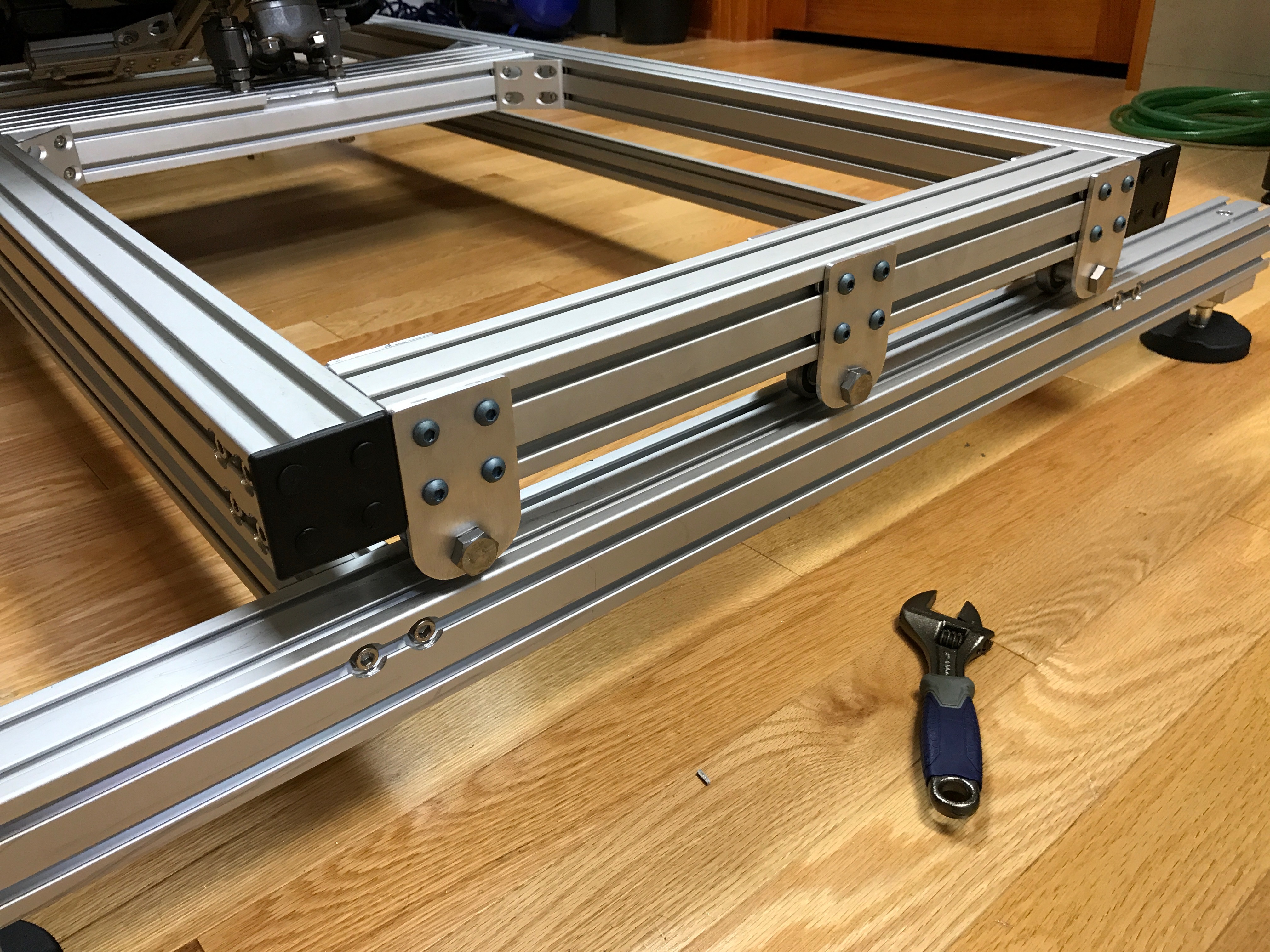\n\nWith the mid frame leveled, I went back to the seat to mount the actuator mount bracket. This was tricky. I had to notch and drill at an angle in the extrusion (98 degrees).\n\n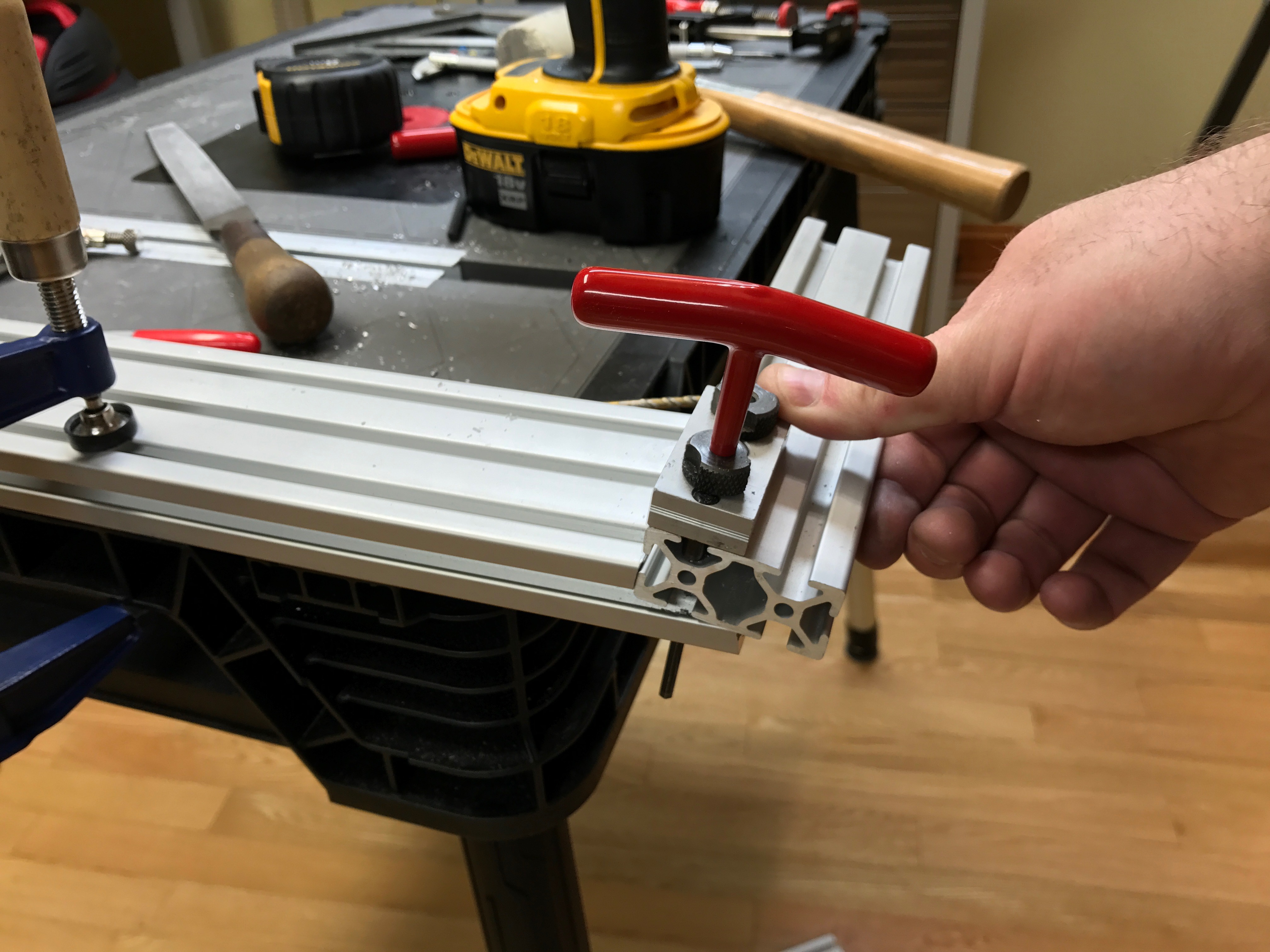\n\nI then designed and fabricated some side support brackets to help relieve the 3 bolts that went into the base extrusion on the seat.\n\n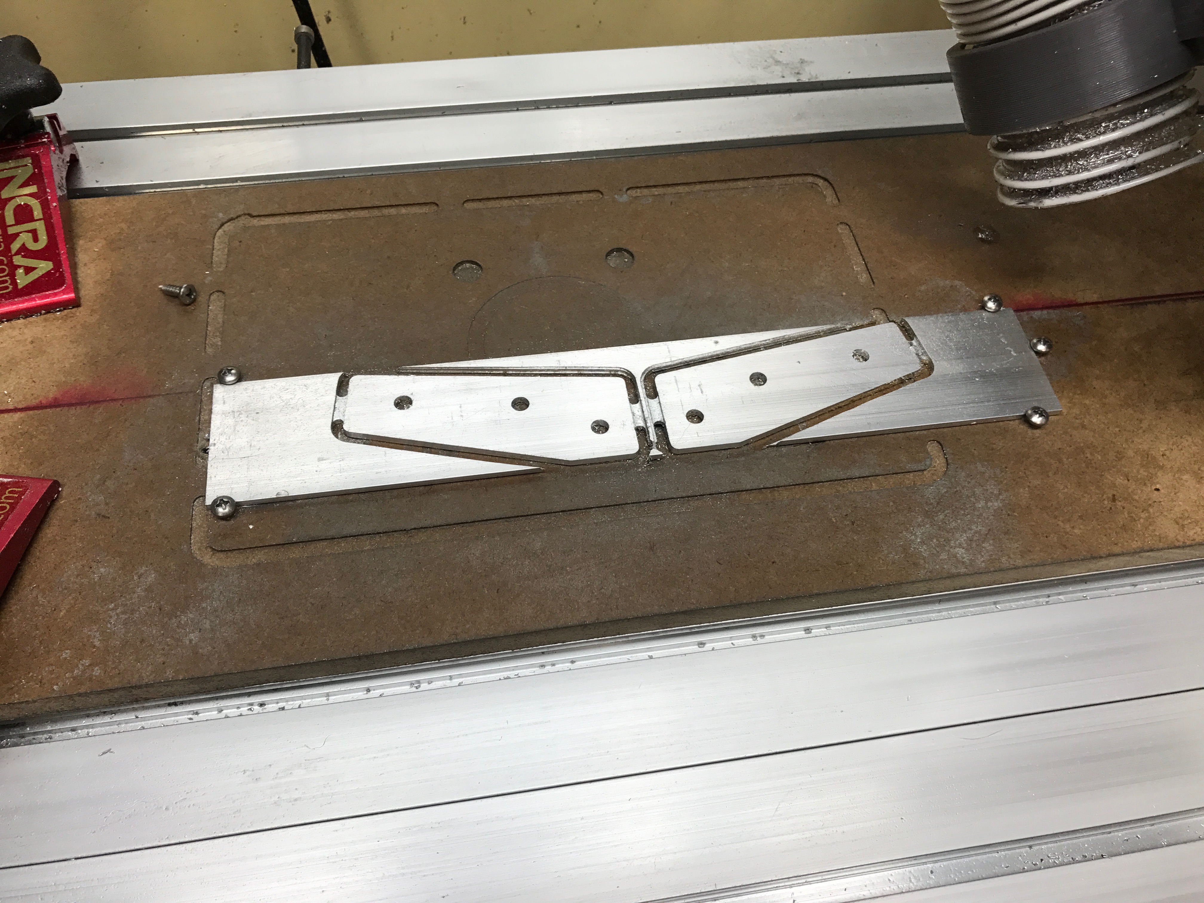\n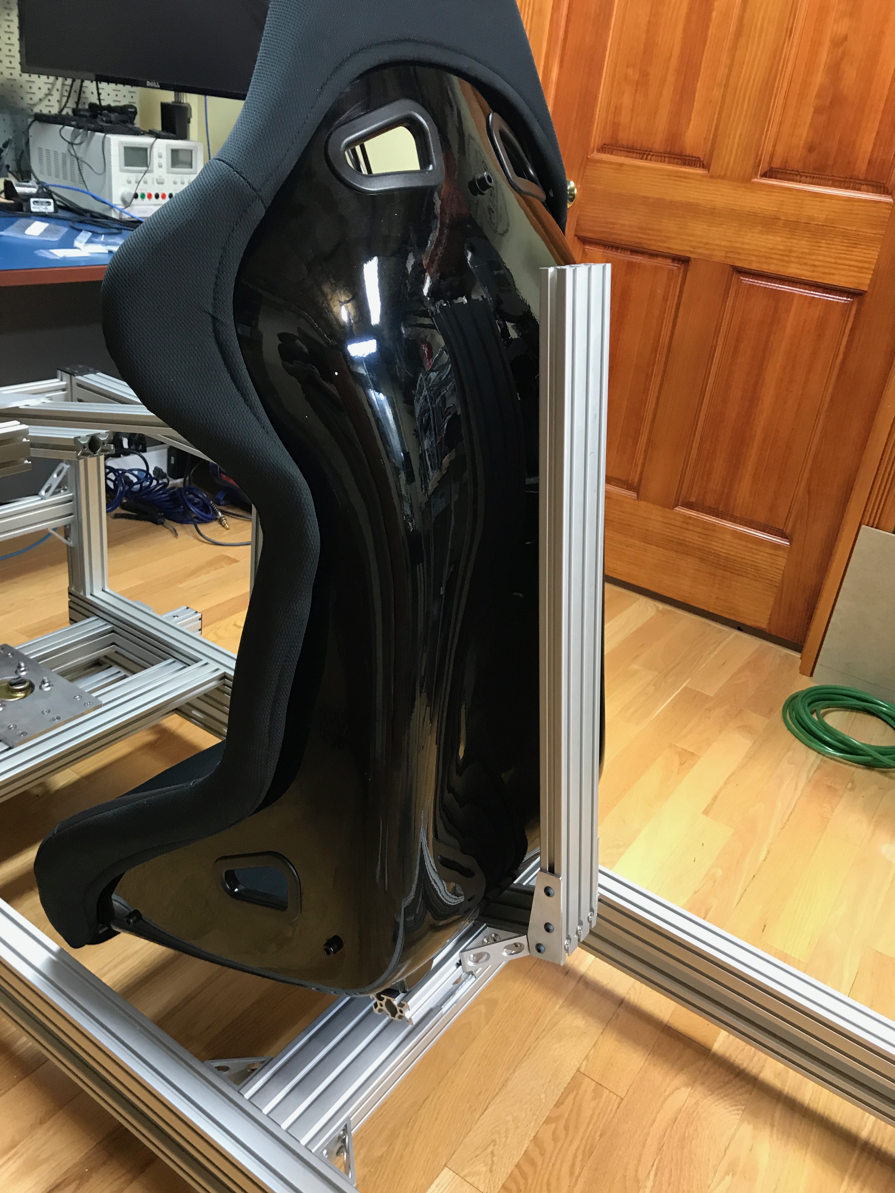\n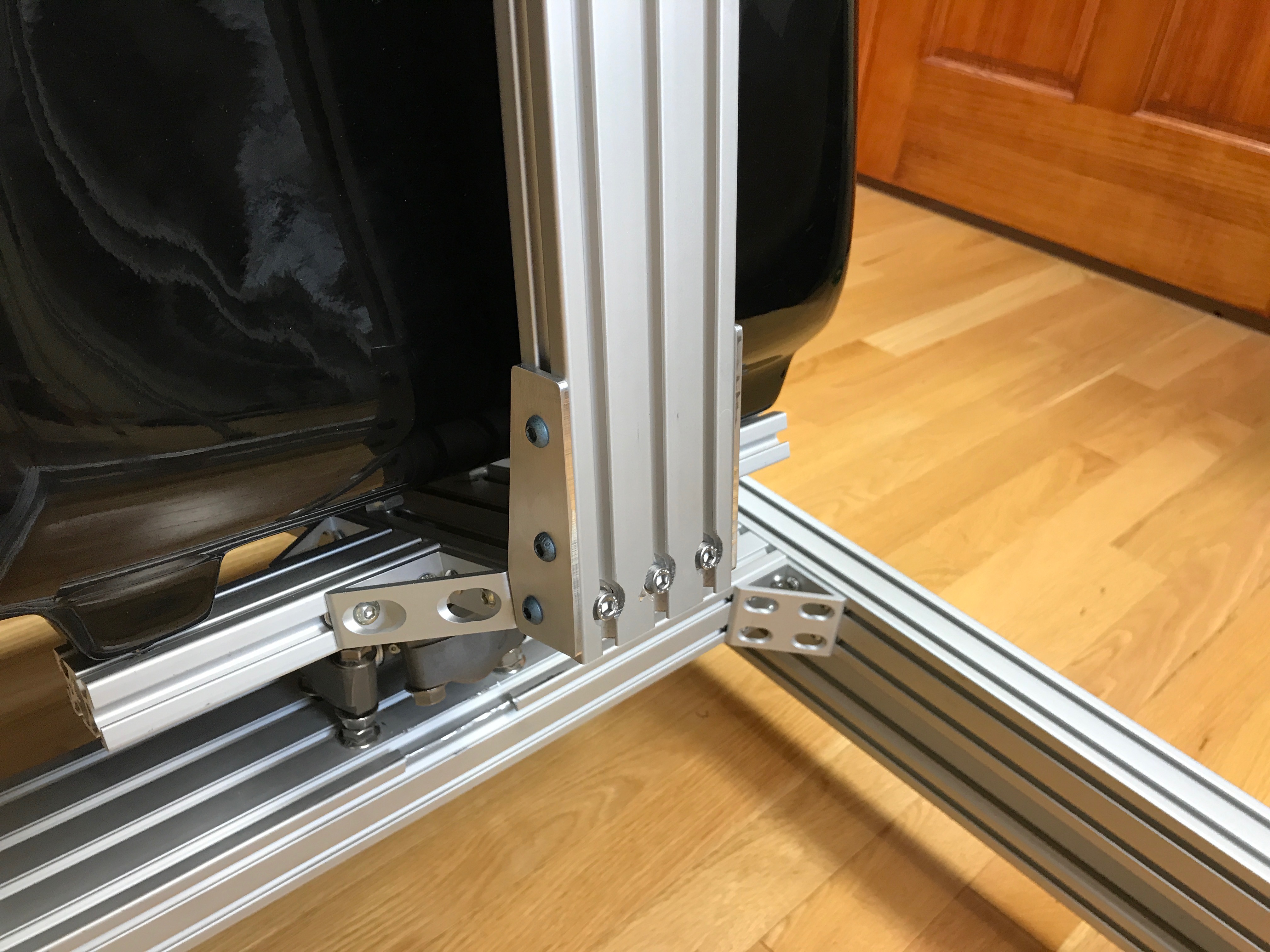\n\nI had to design and fabricate end caps for the extrusion that would allow me to thread tap for the actuators. This was the thickest aluminum stock that I had milled on my CNC at the time. Everything went ok-ish... Mid job the x-axis coupler came loose and the CNC started to dig into the piece. I was able to stop it and recover the job without any major damage.\n\n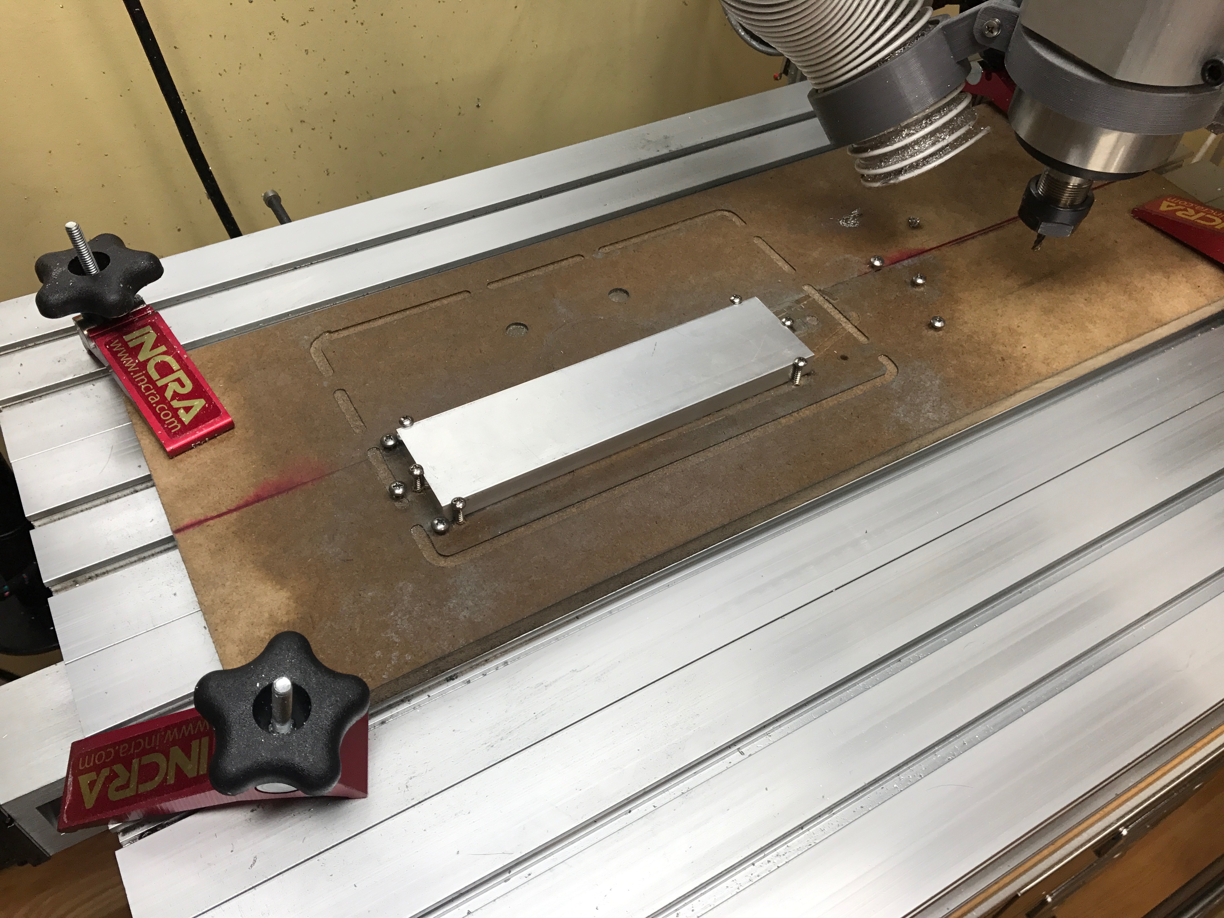\n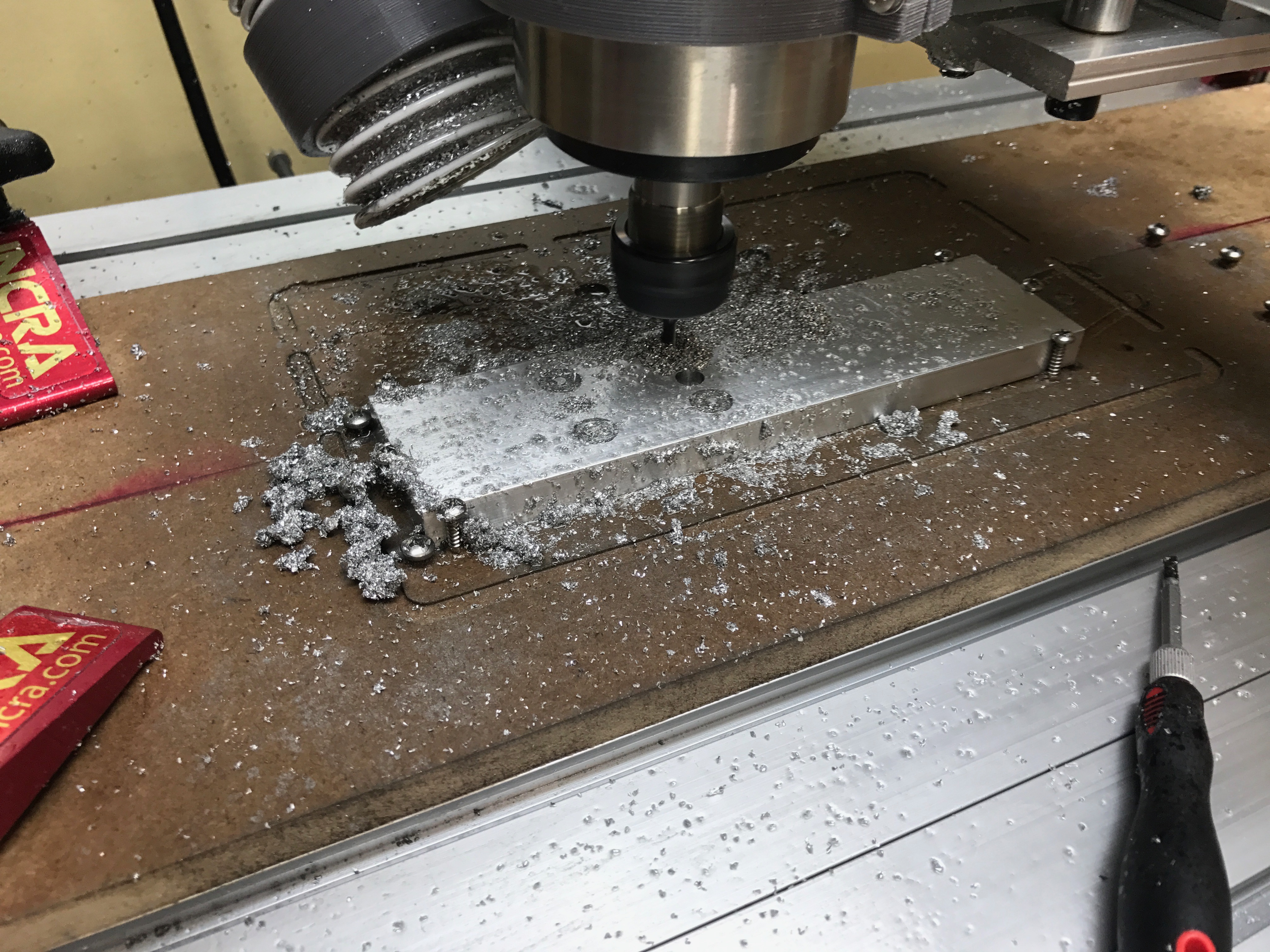\n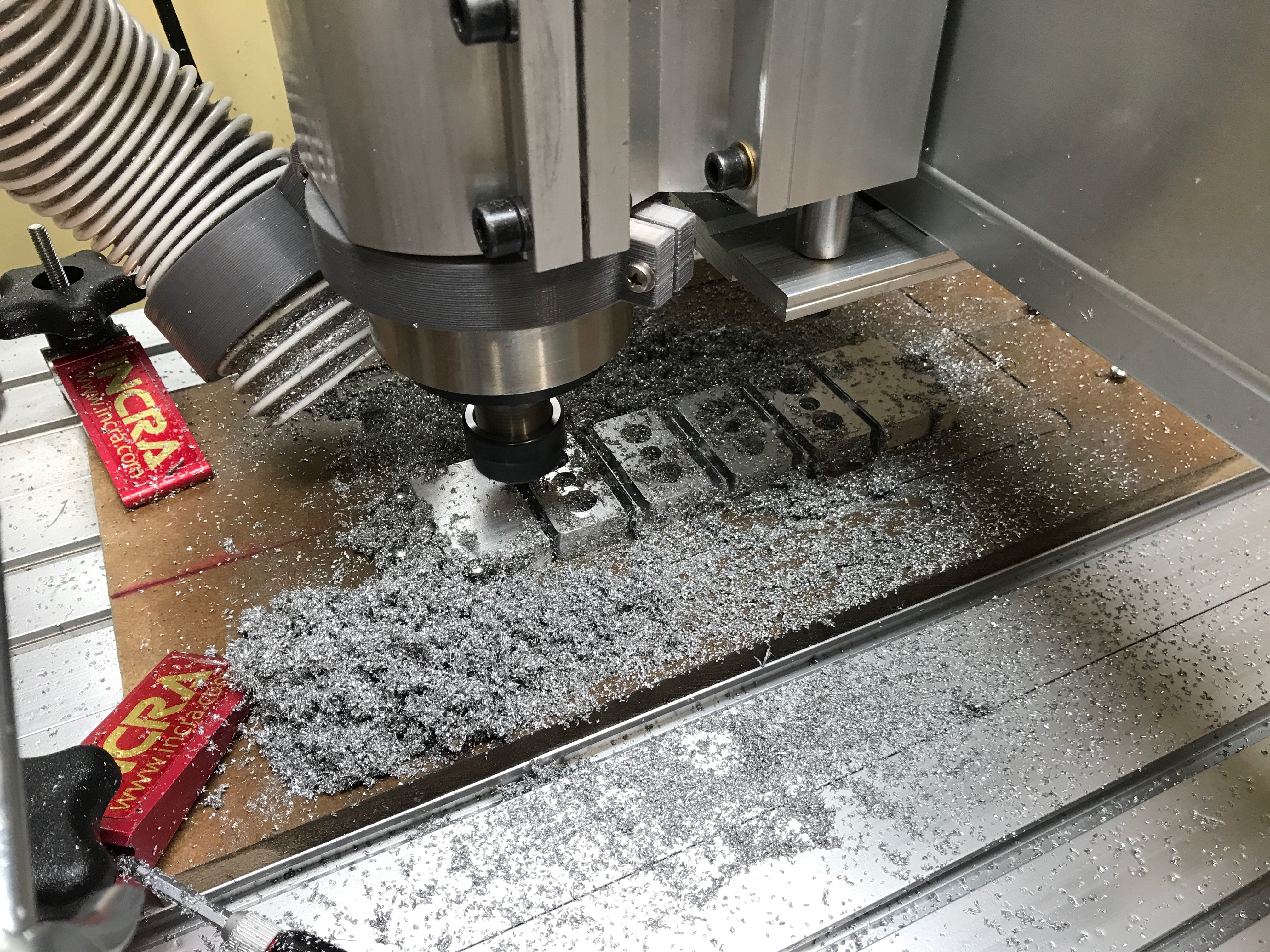\n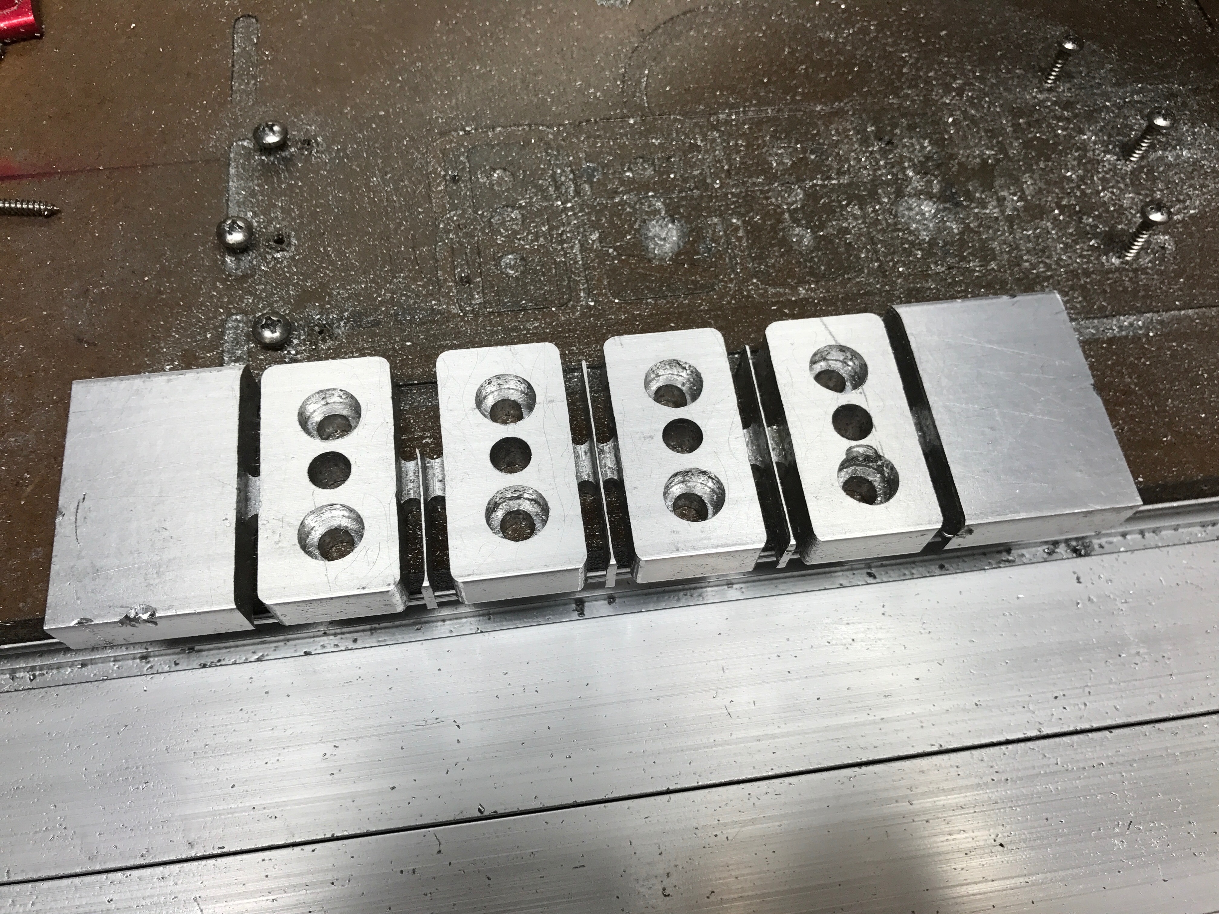\n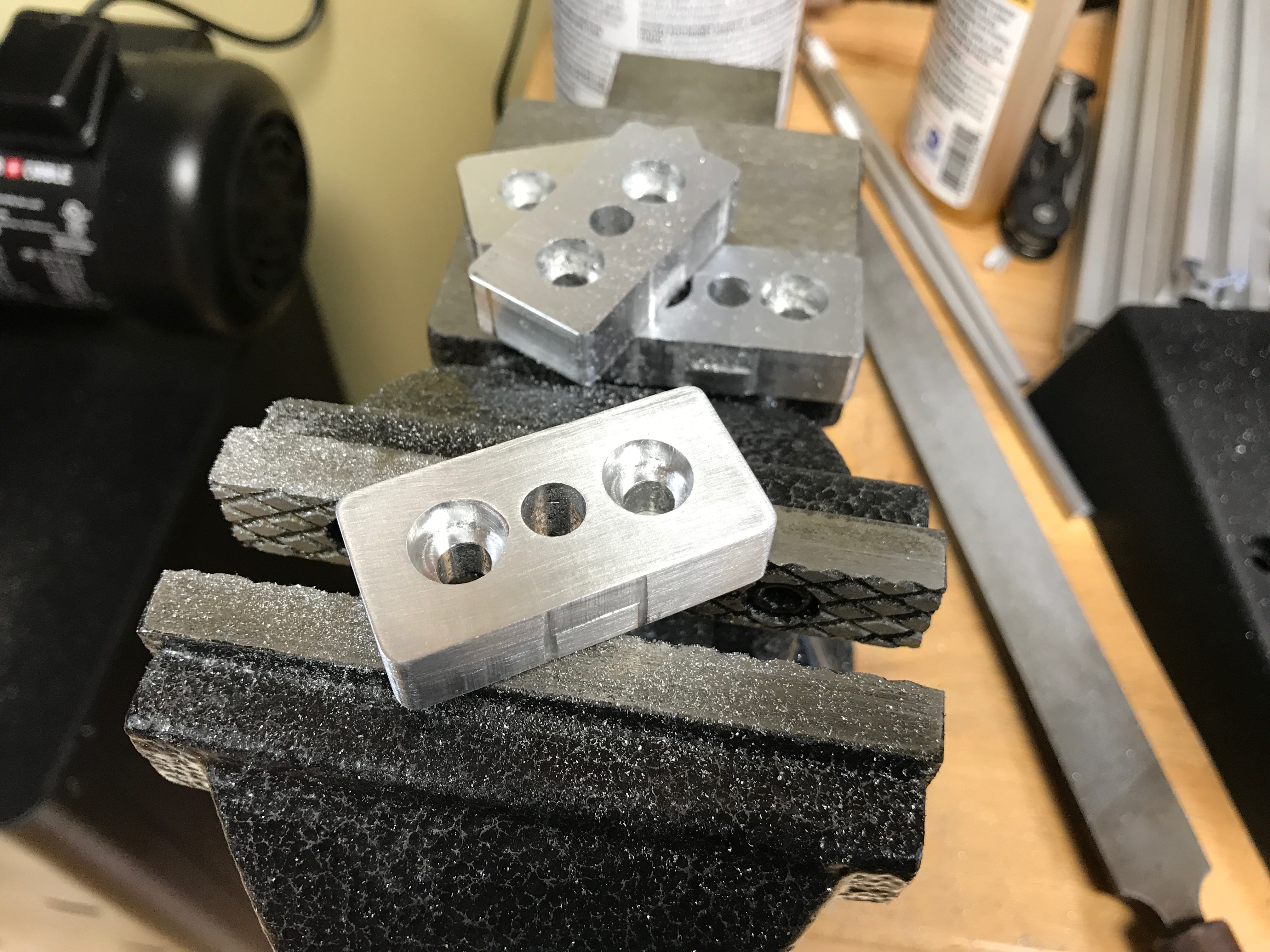\n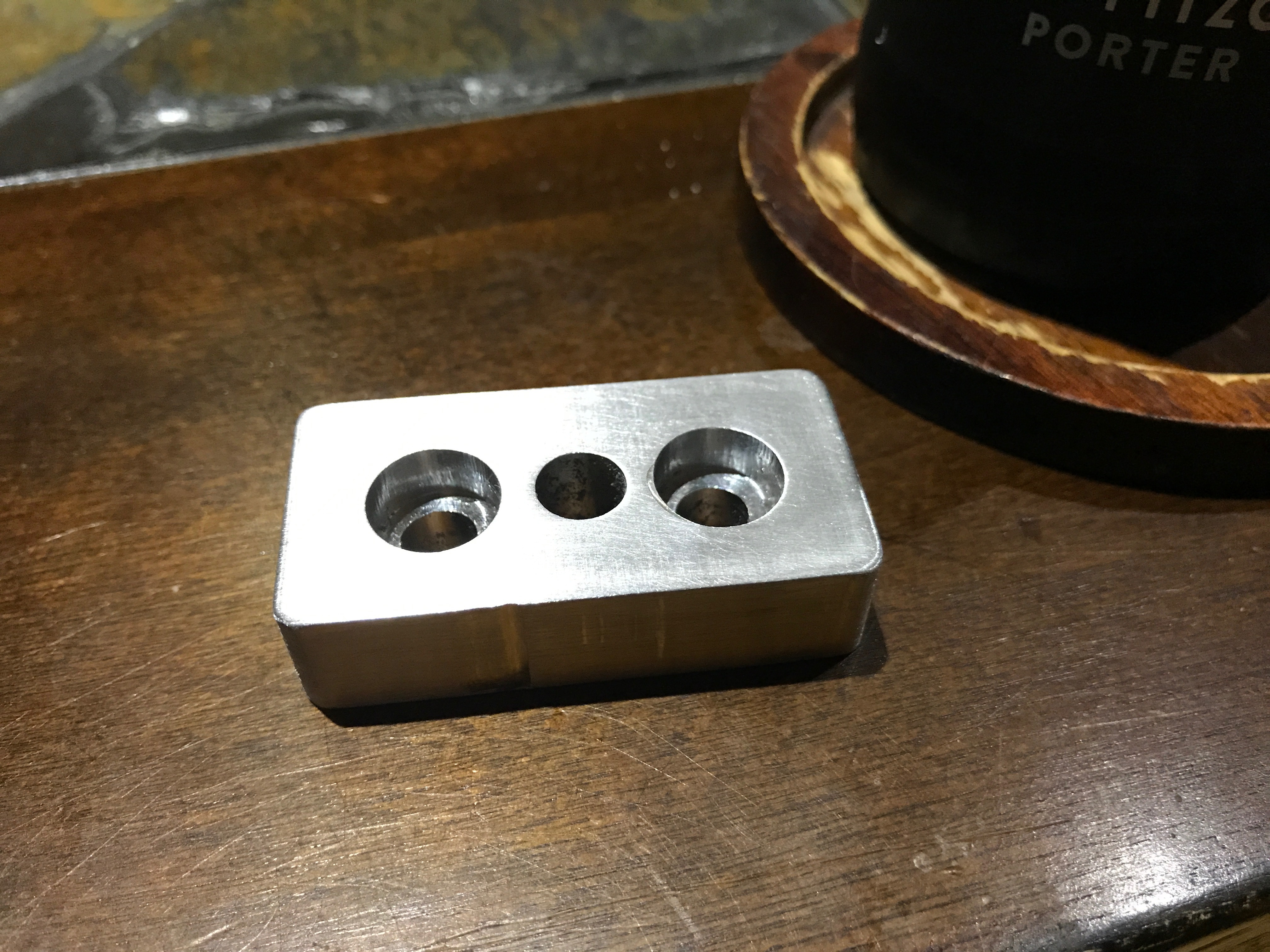\n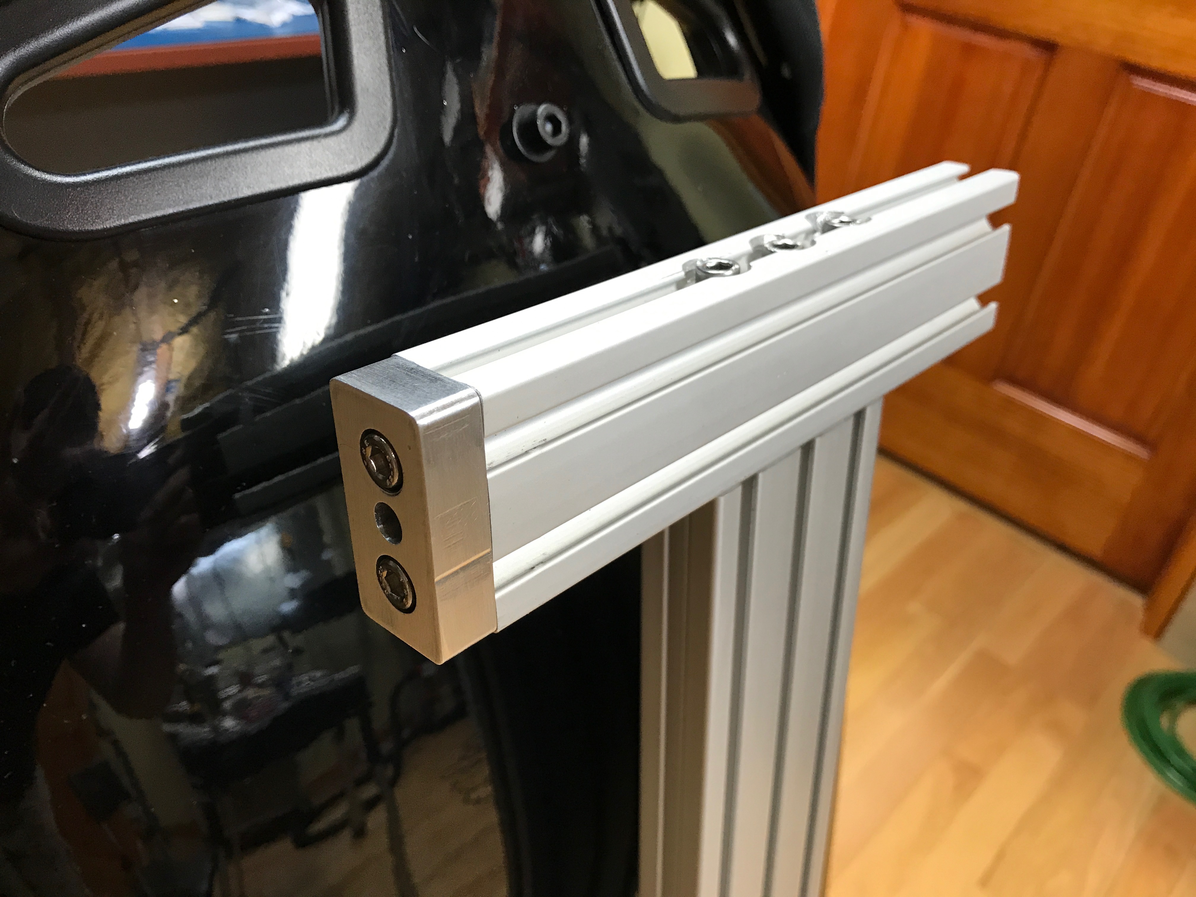\n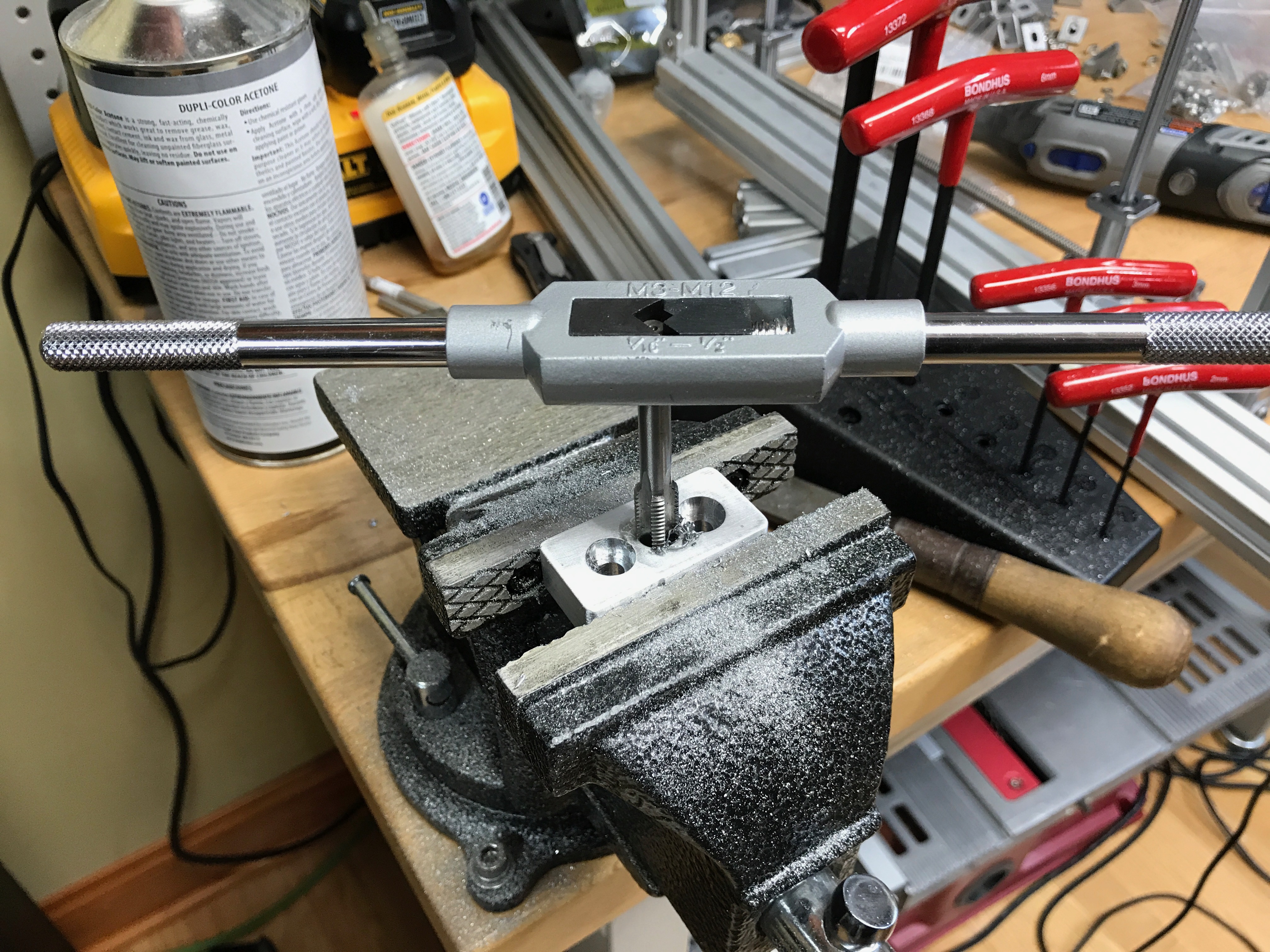\n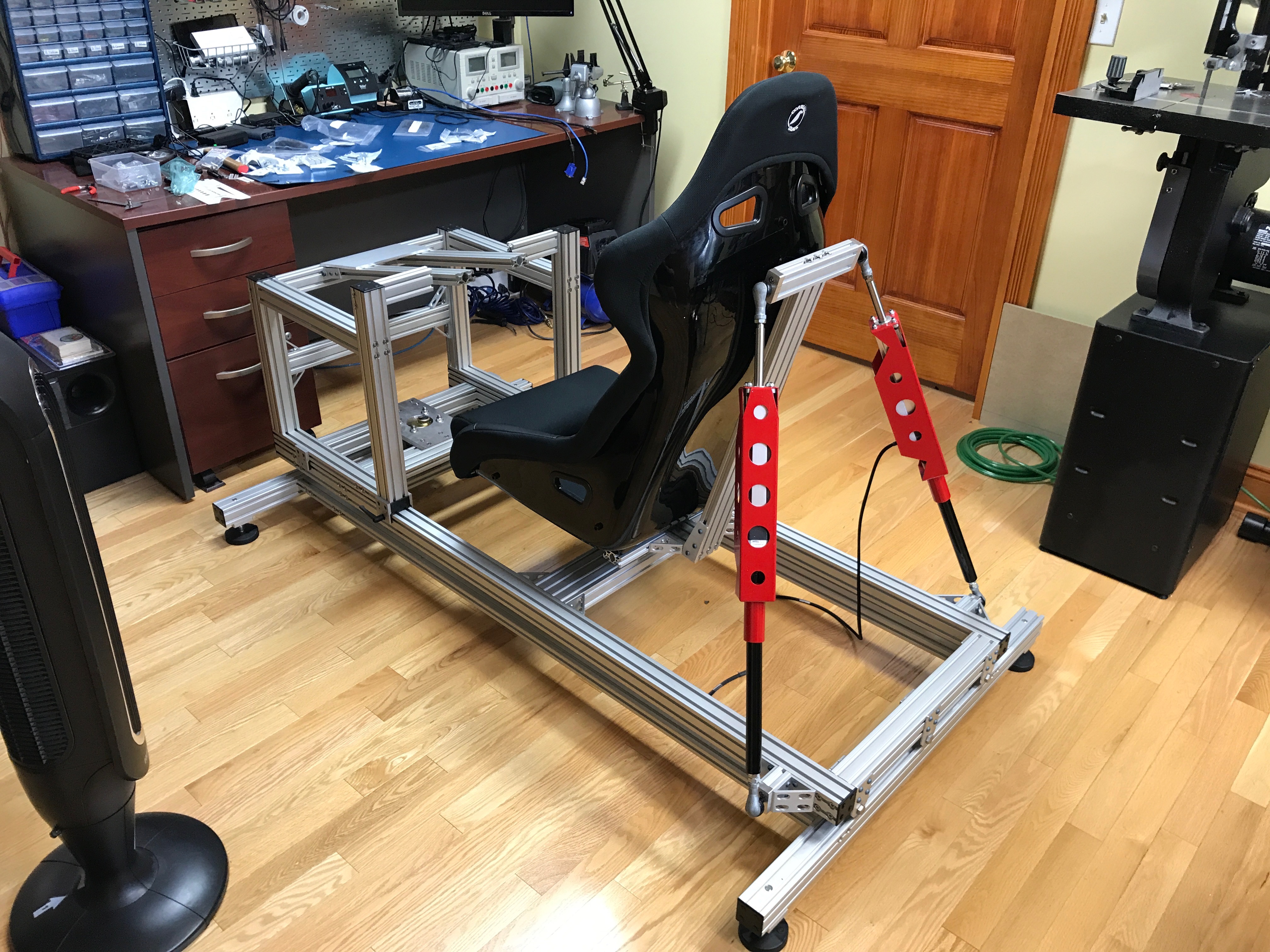\n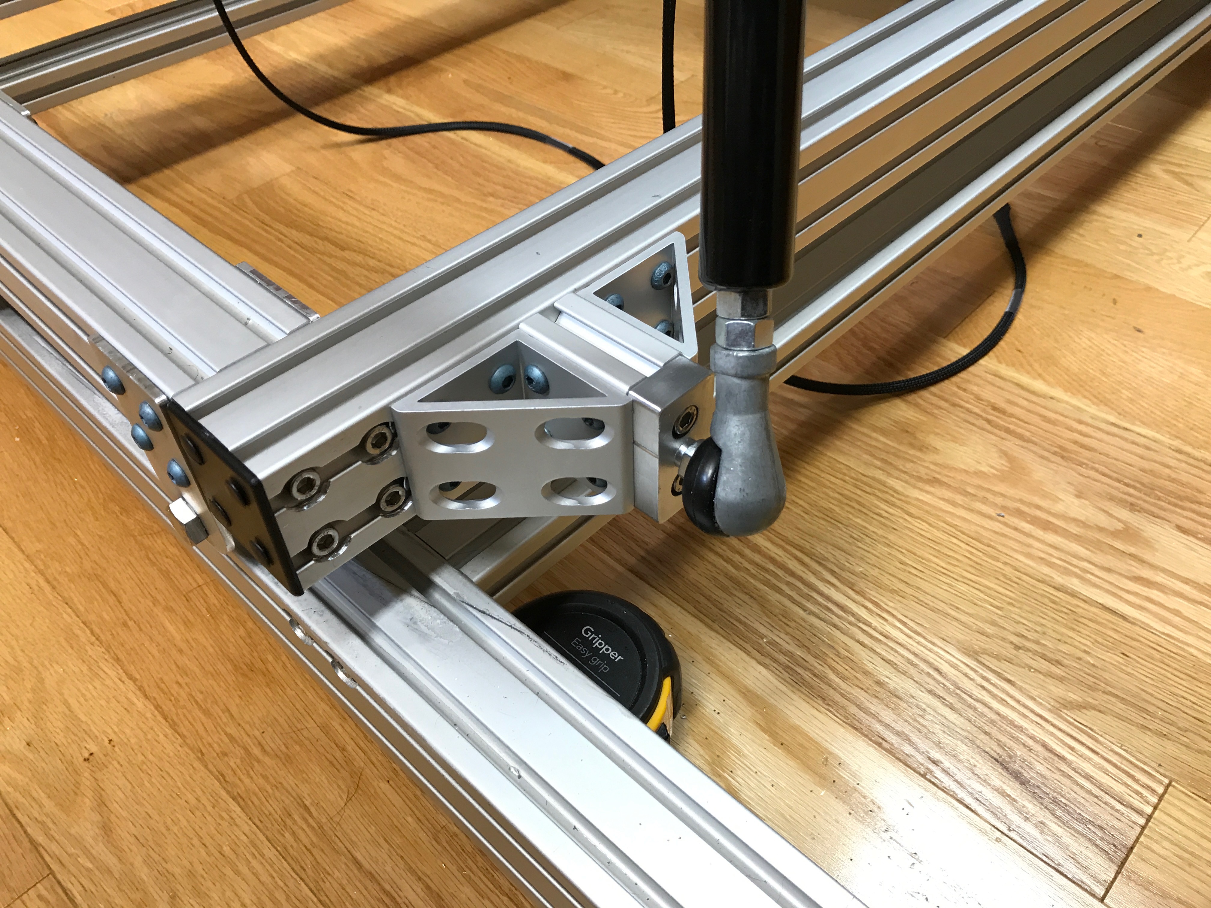\n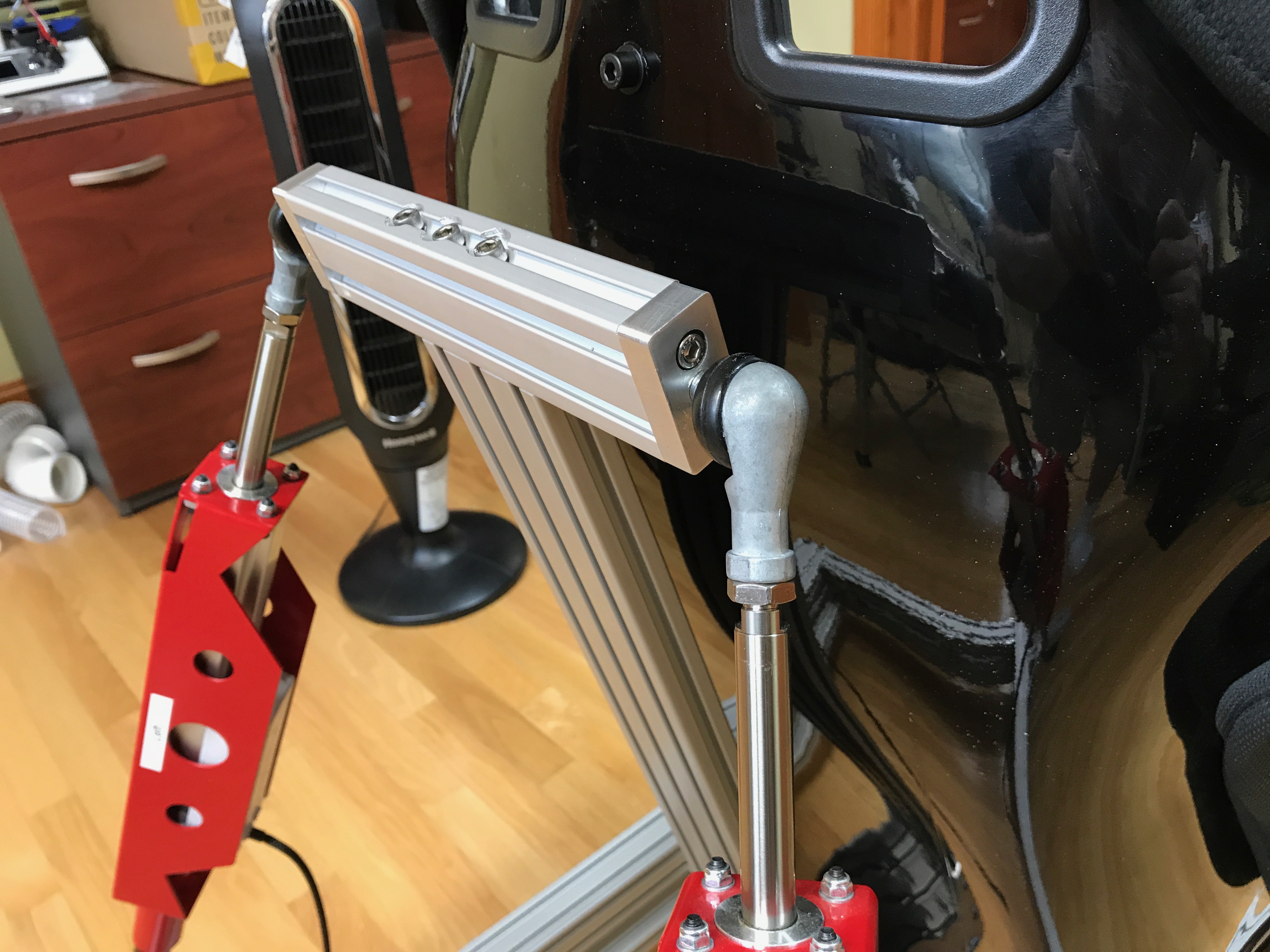\n\nThe rear traction loss actuator needed a pair of brackets. Again, designed in Fusion360, then milled on my CNC.\n\n\u003cp align=\"center\"\u003e\n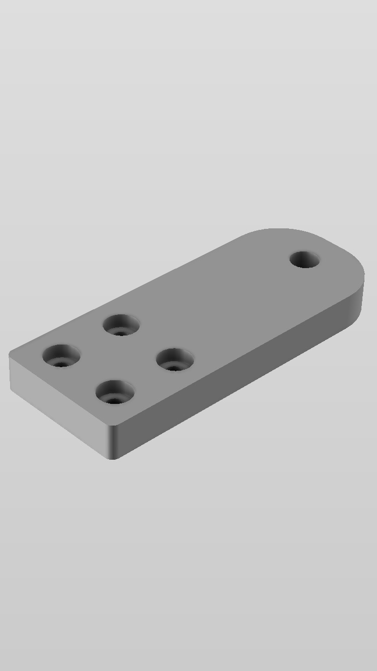\n\u003c/p\u003e\n\n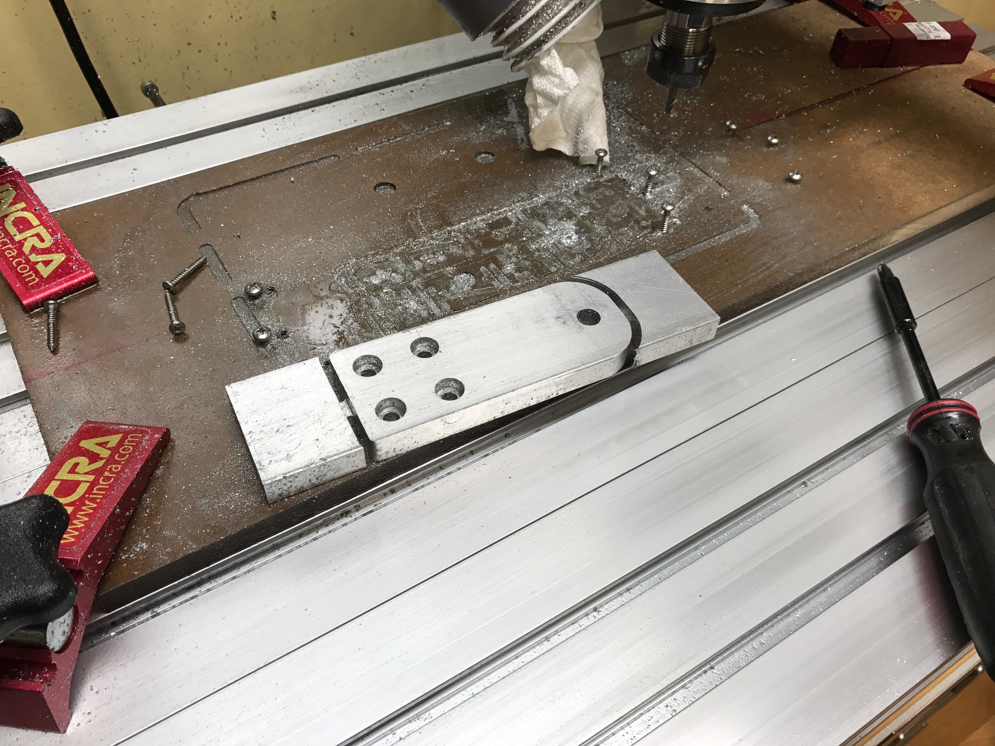\n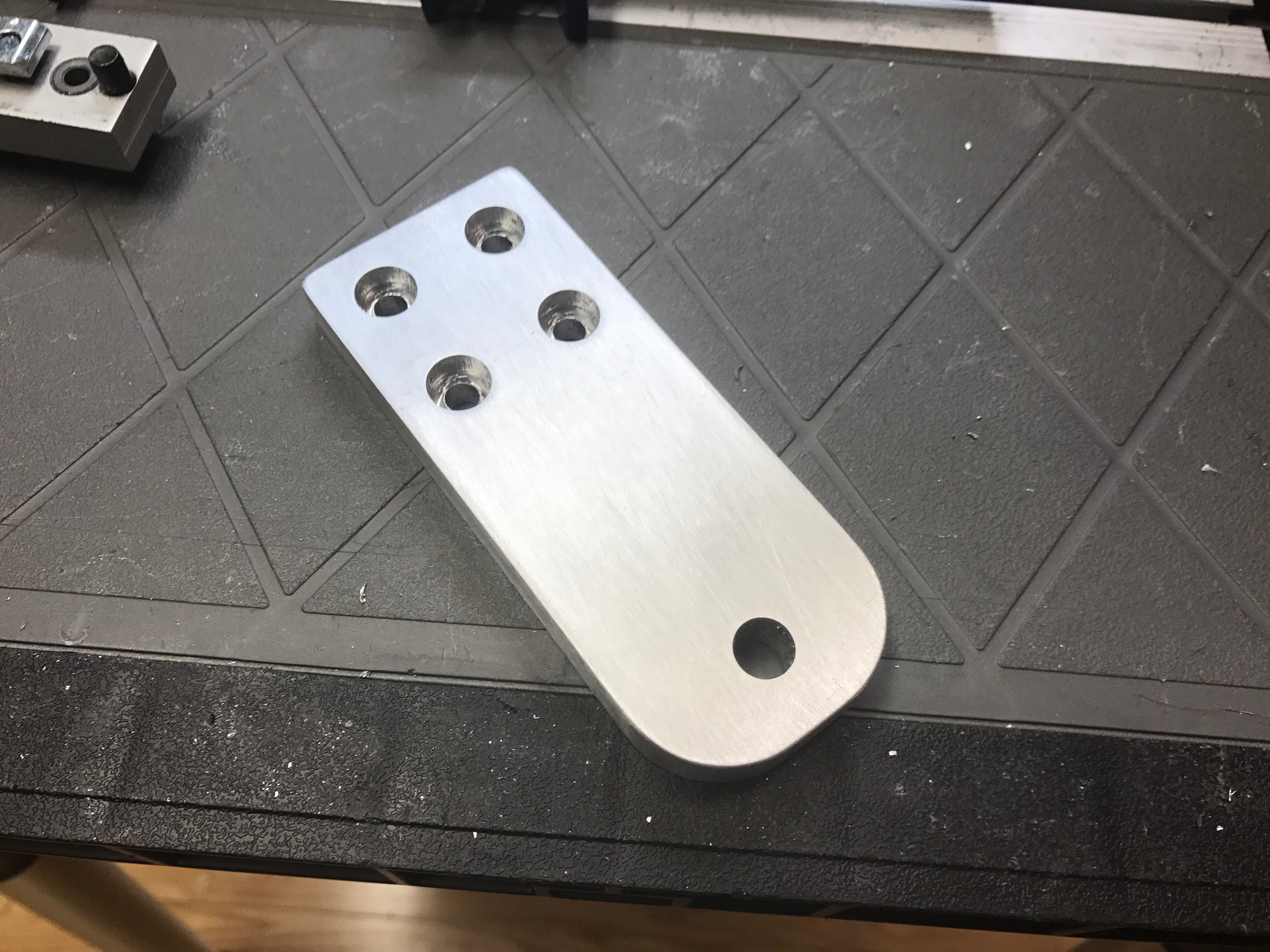\n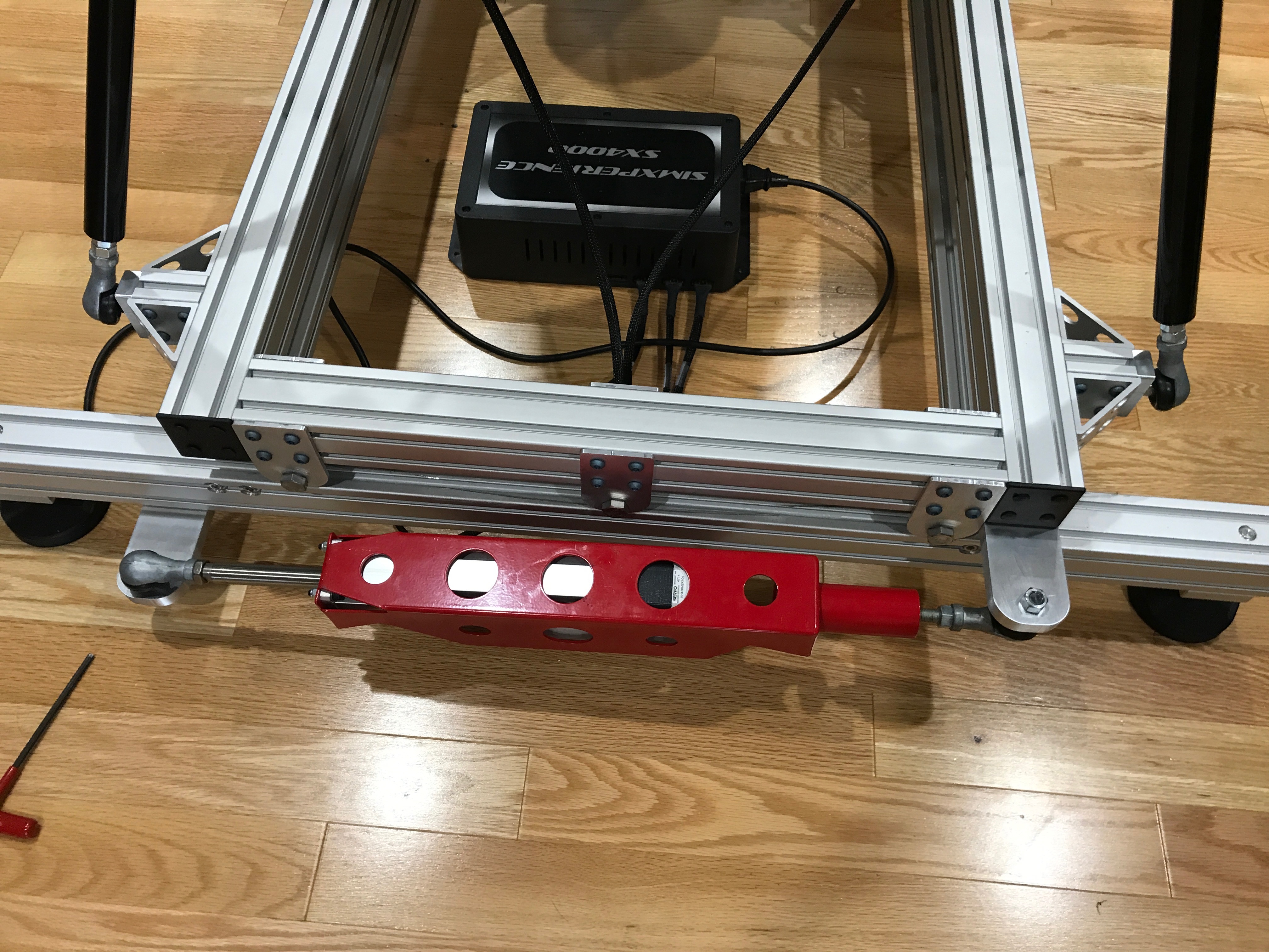\n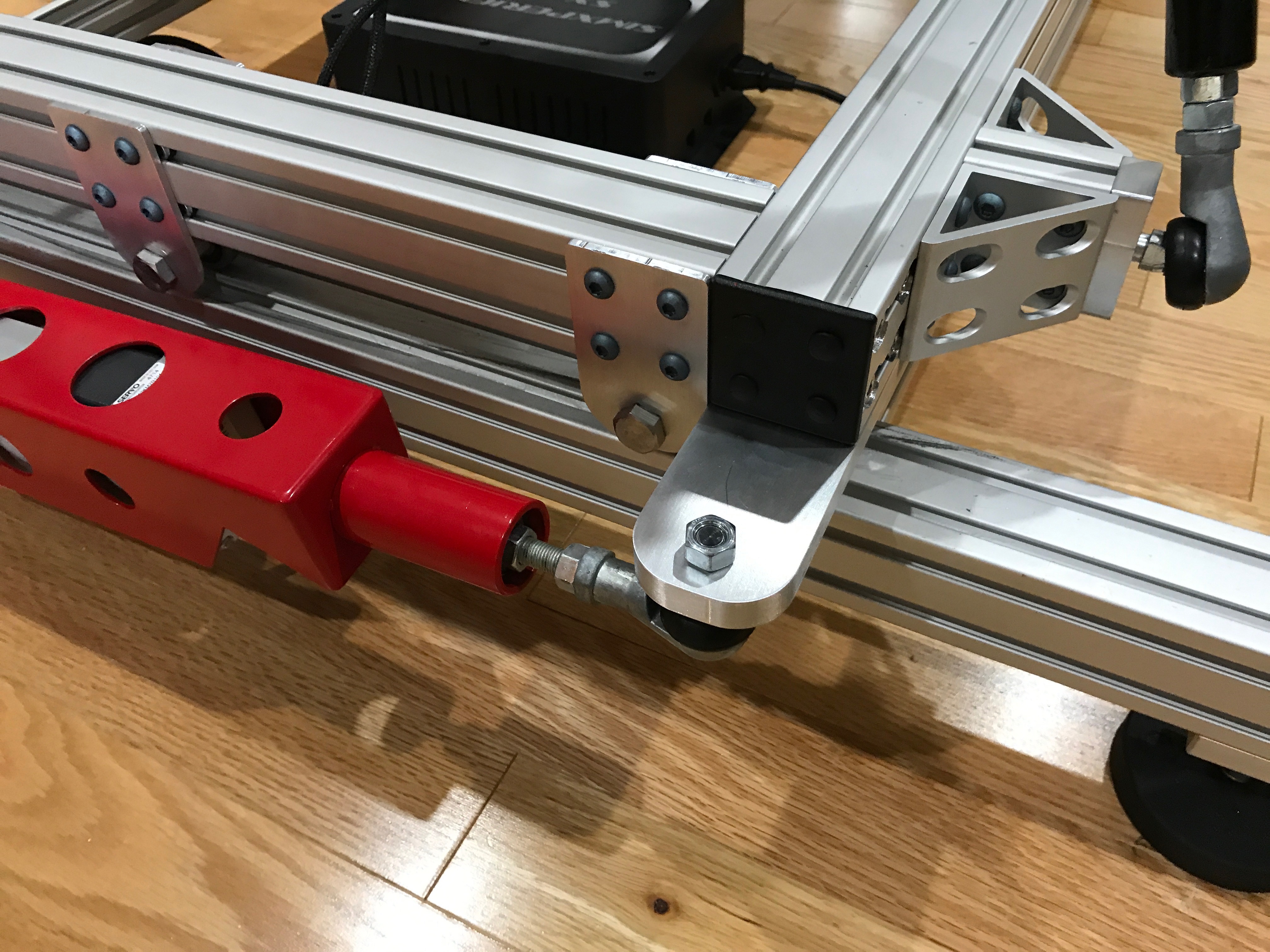\n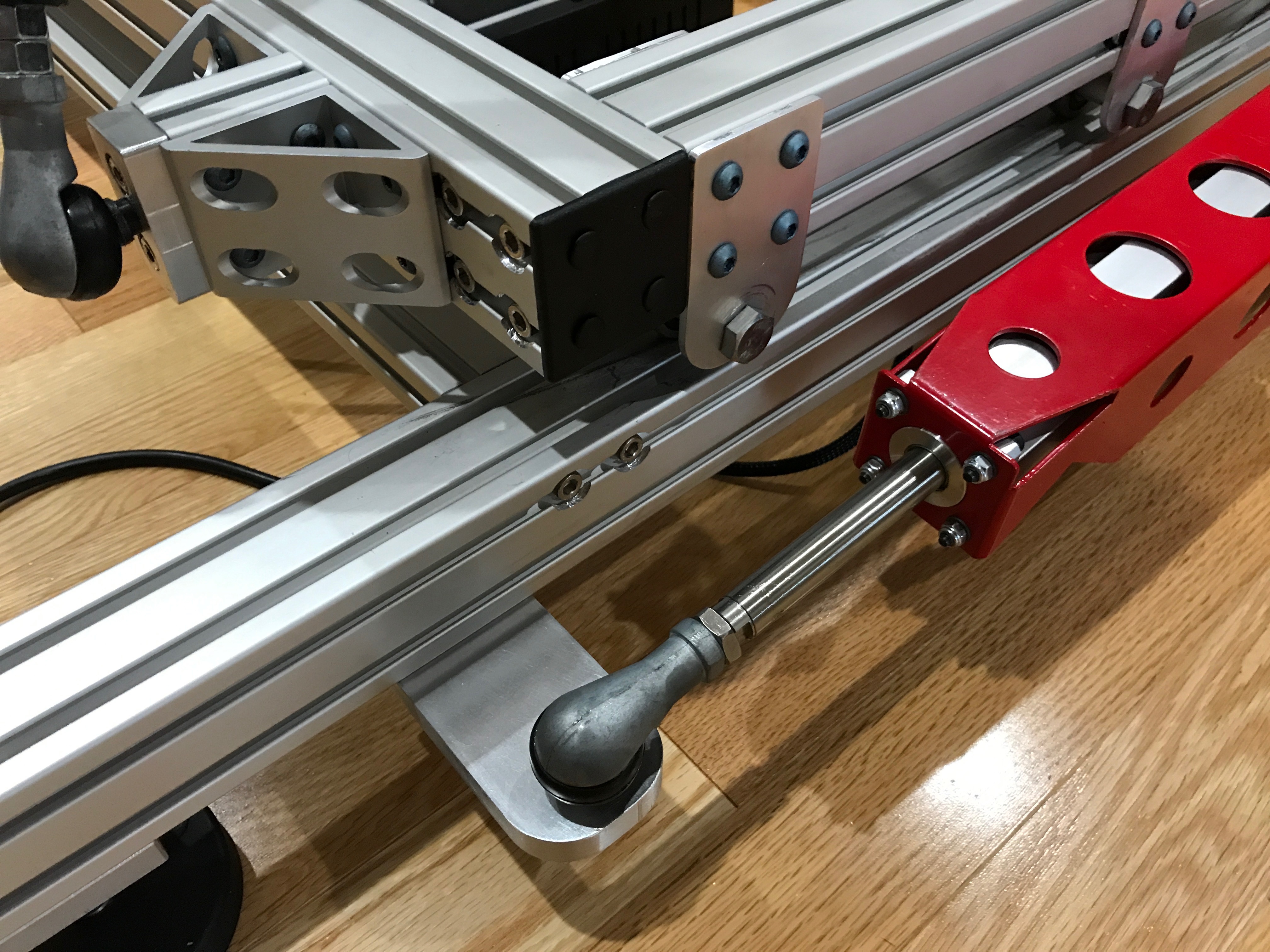\n\nI marked and drilled out the mounting plate for the steering wheel. This was just a piece of stock that I purchased from [80/20 Inc](https://8020.net).\n\n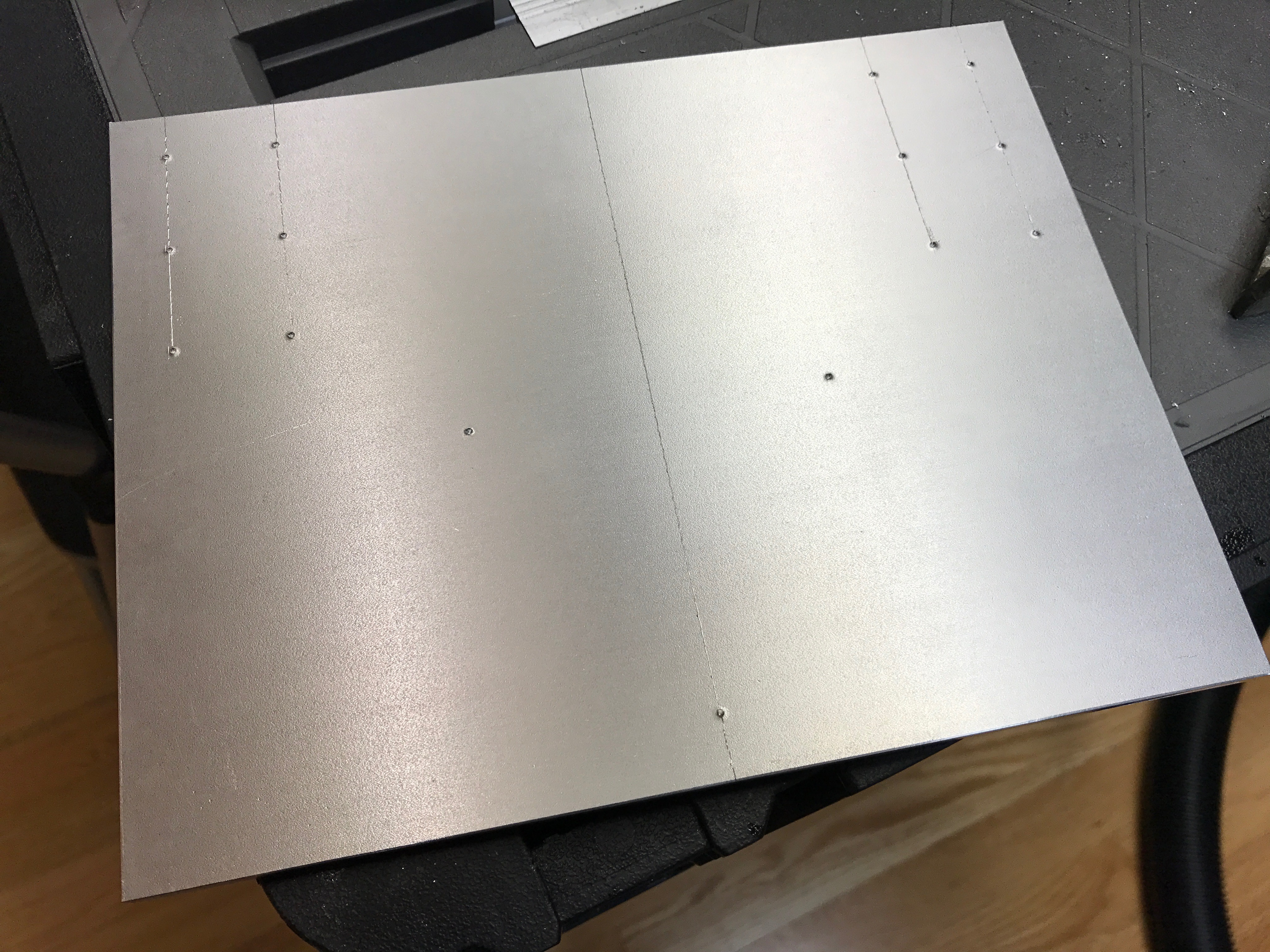\n\nThen designed and milled the brackets for the steering height adjustment.\n\n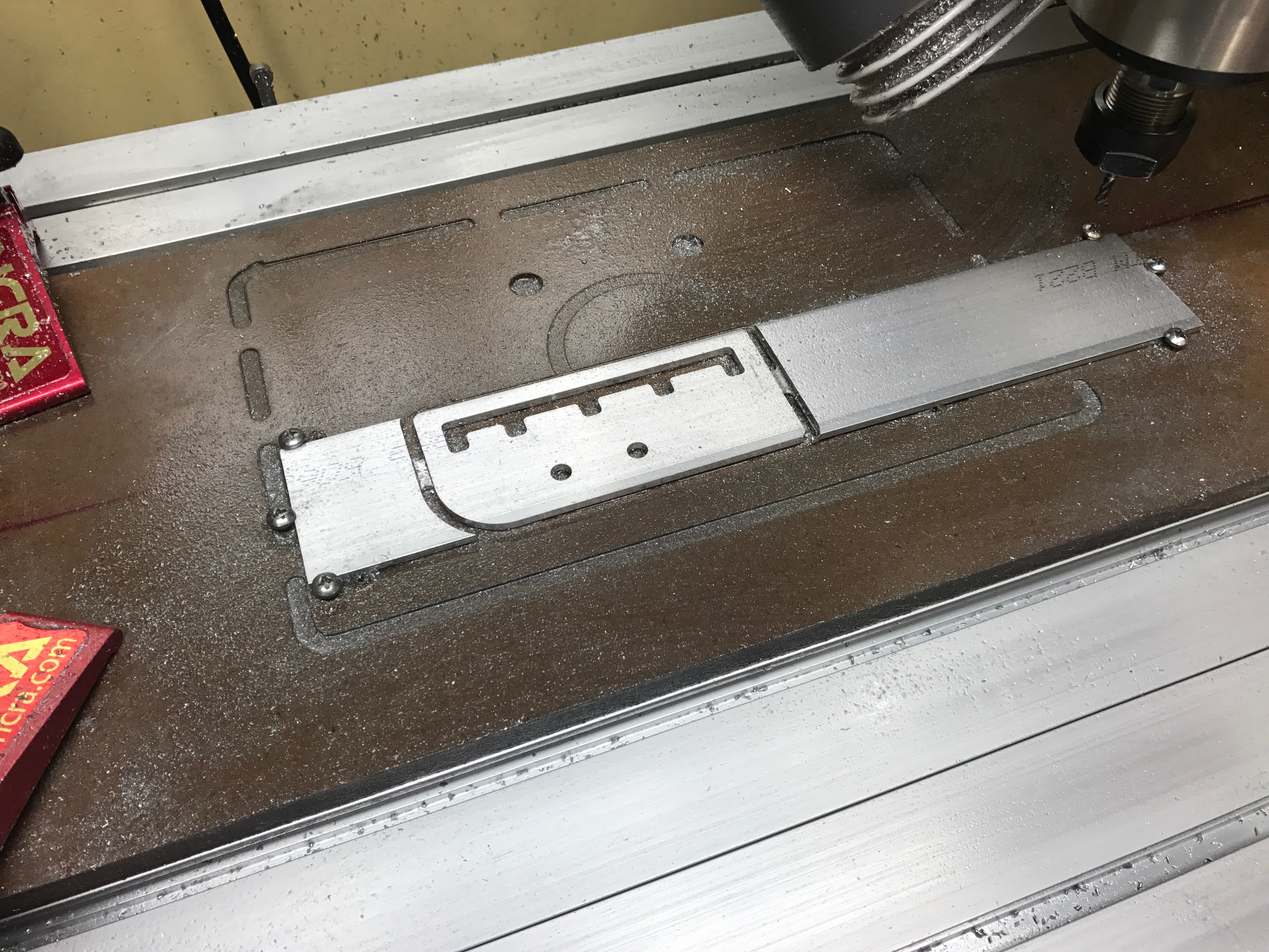\n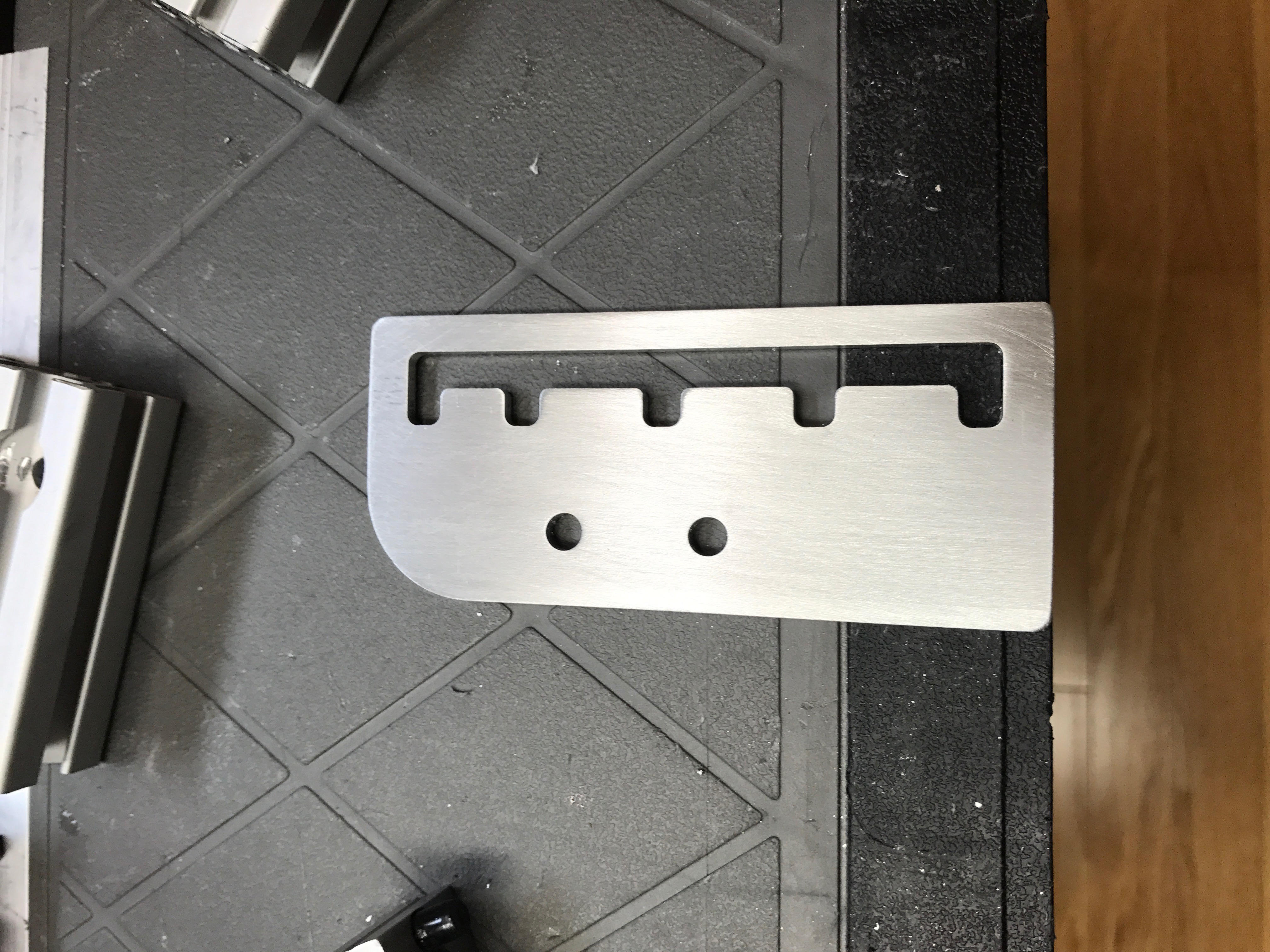\n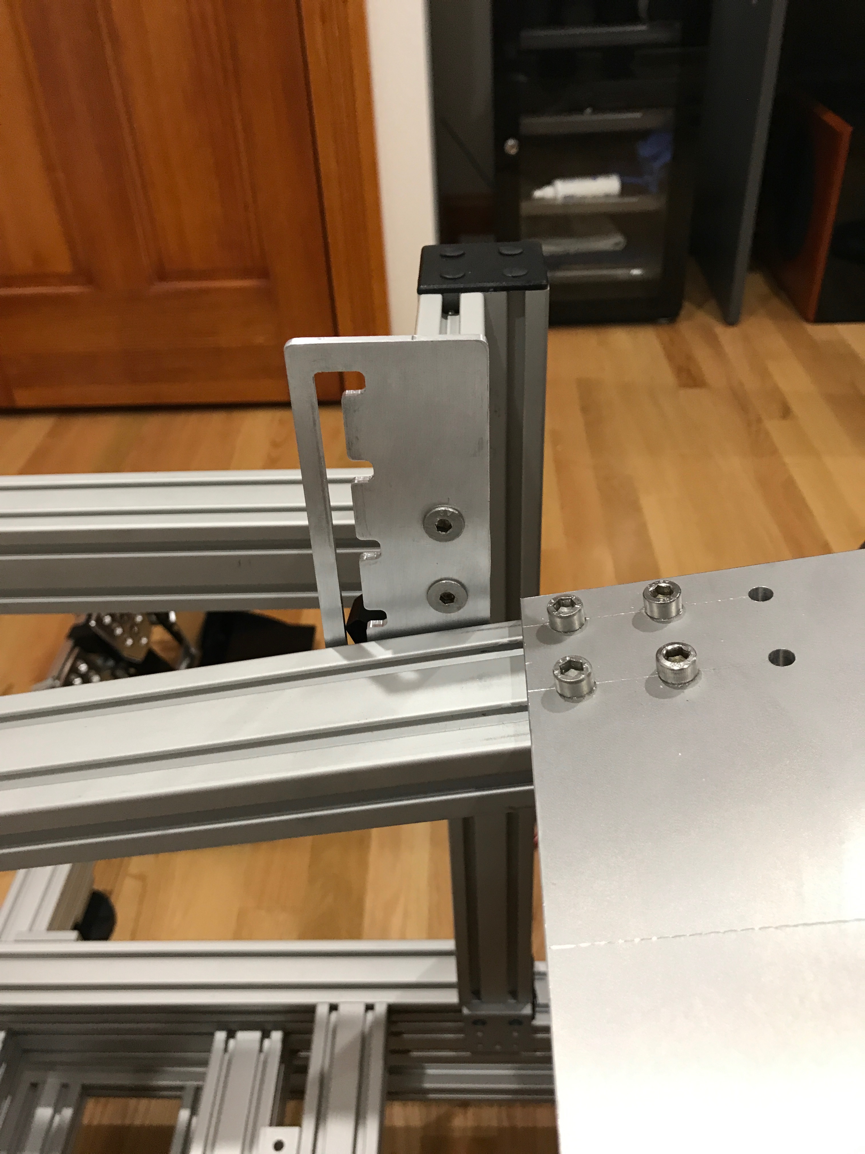\n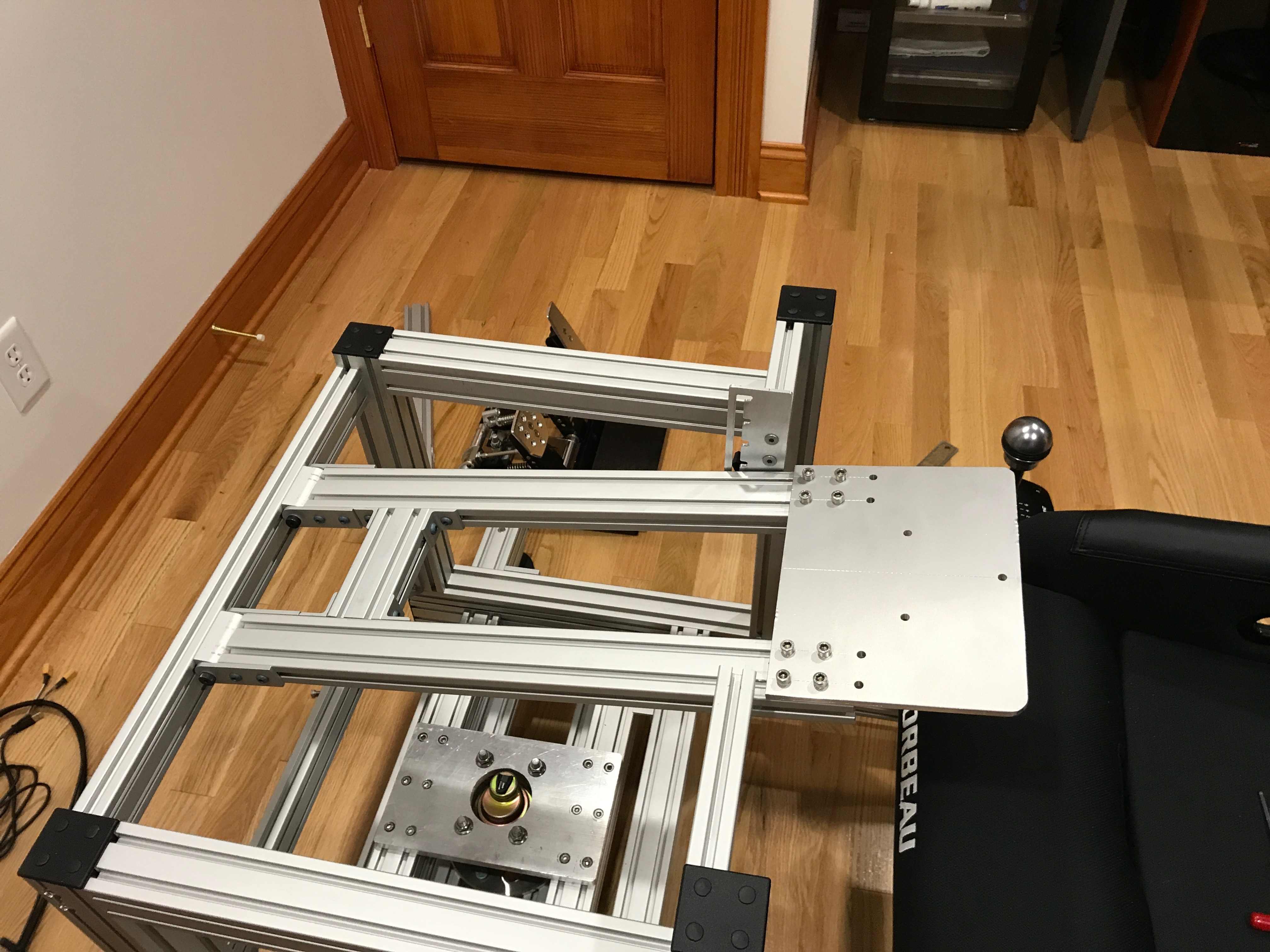\n\nMounting the shifter and handbrake was pretty straight forward. I was able to use 80/20 components for the shifter and I re-used the version 1 handbrake mount with slight modification.\n\n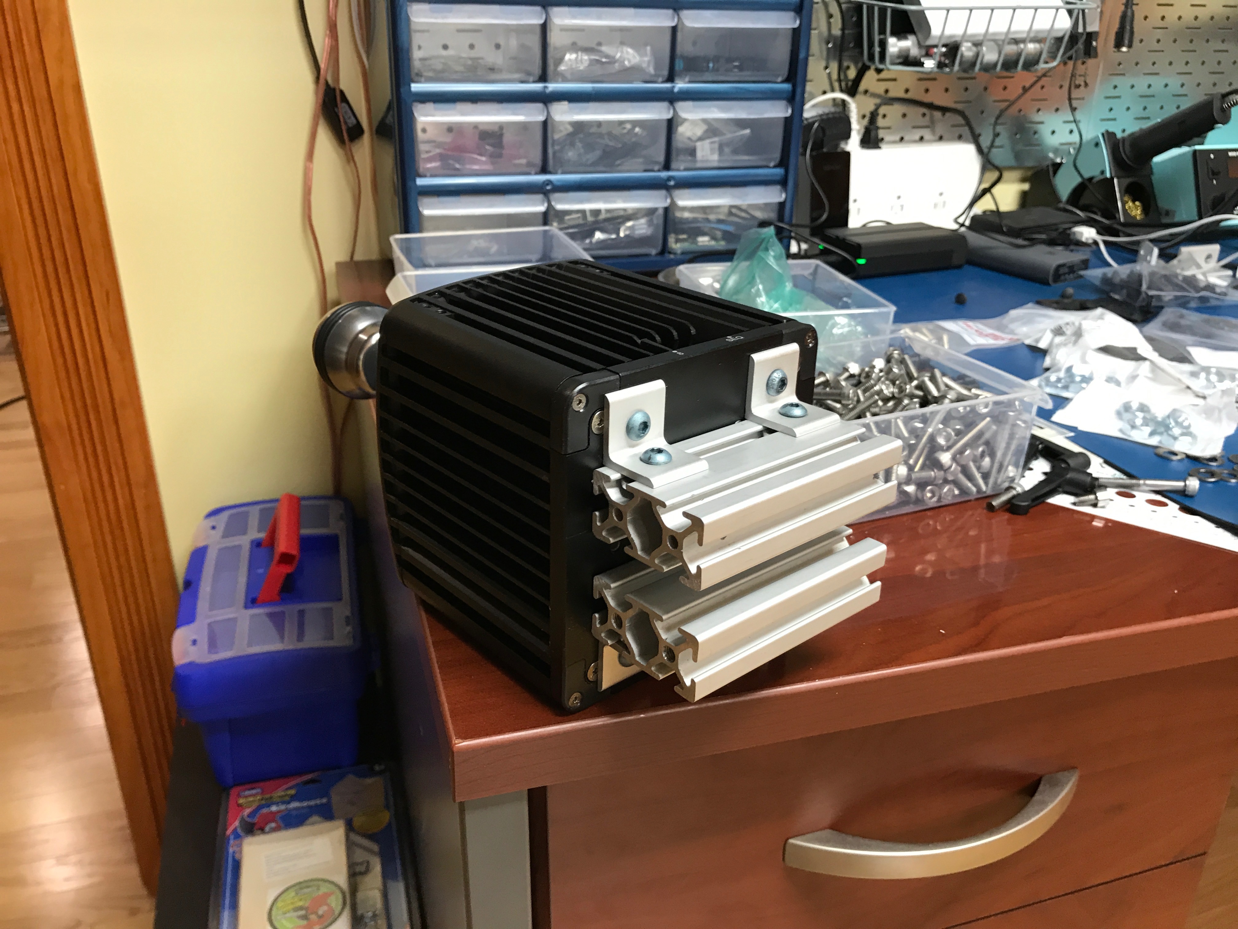\n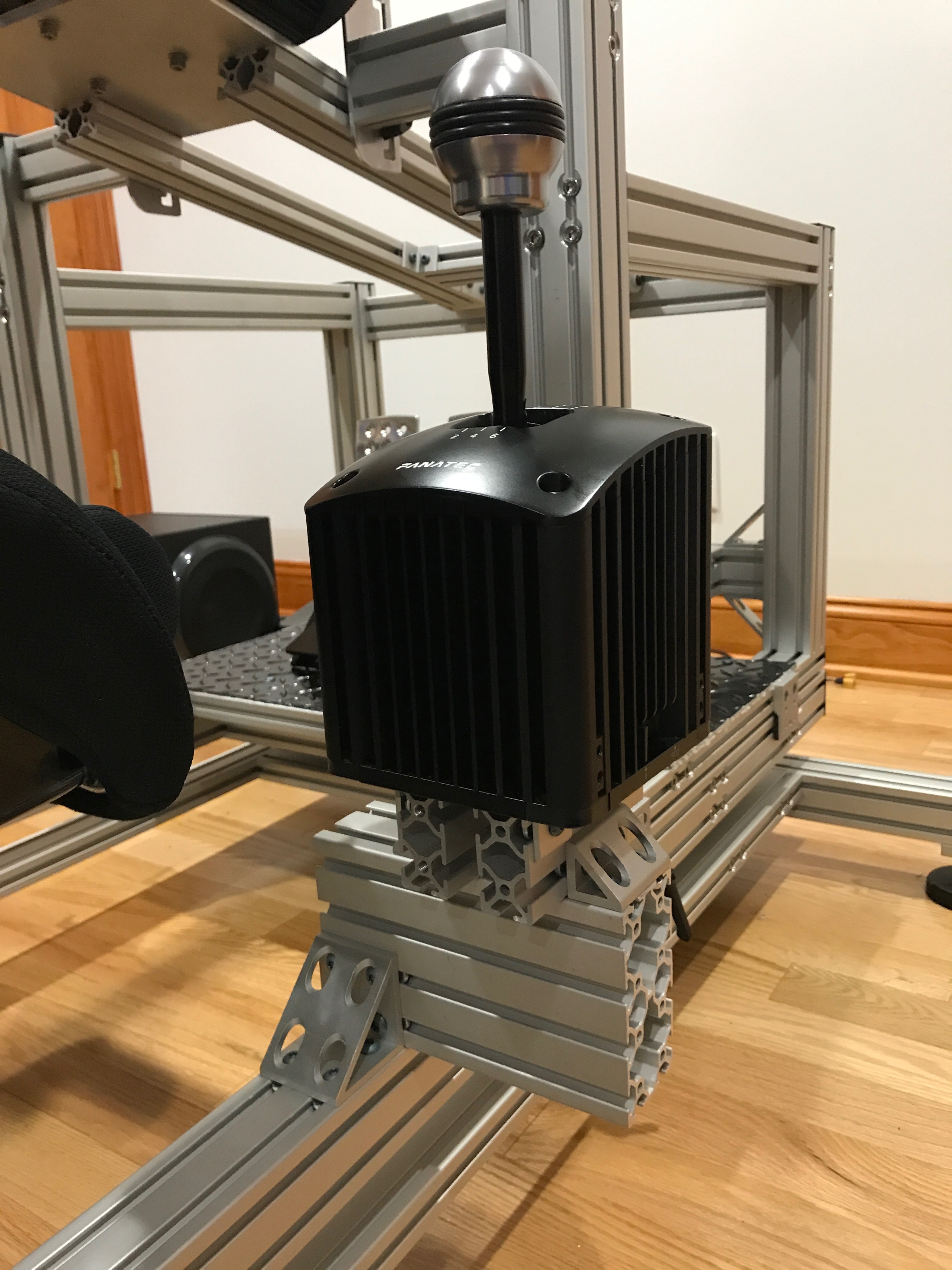\n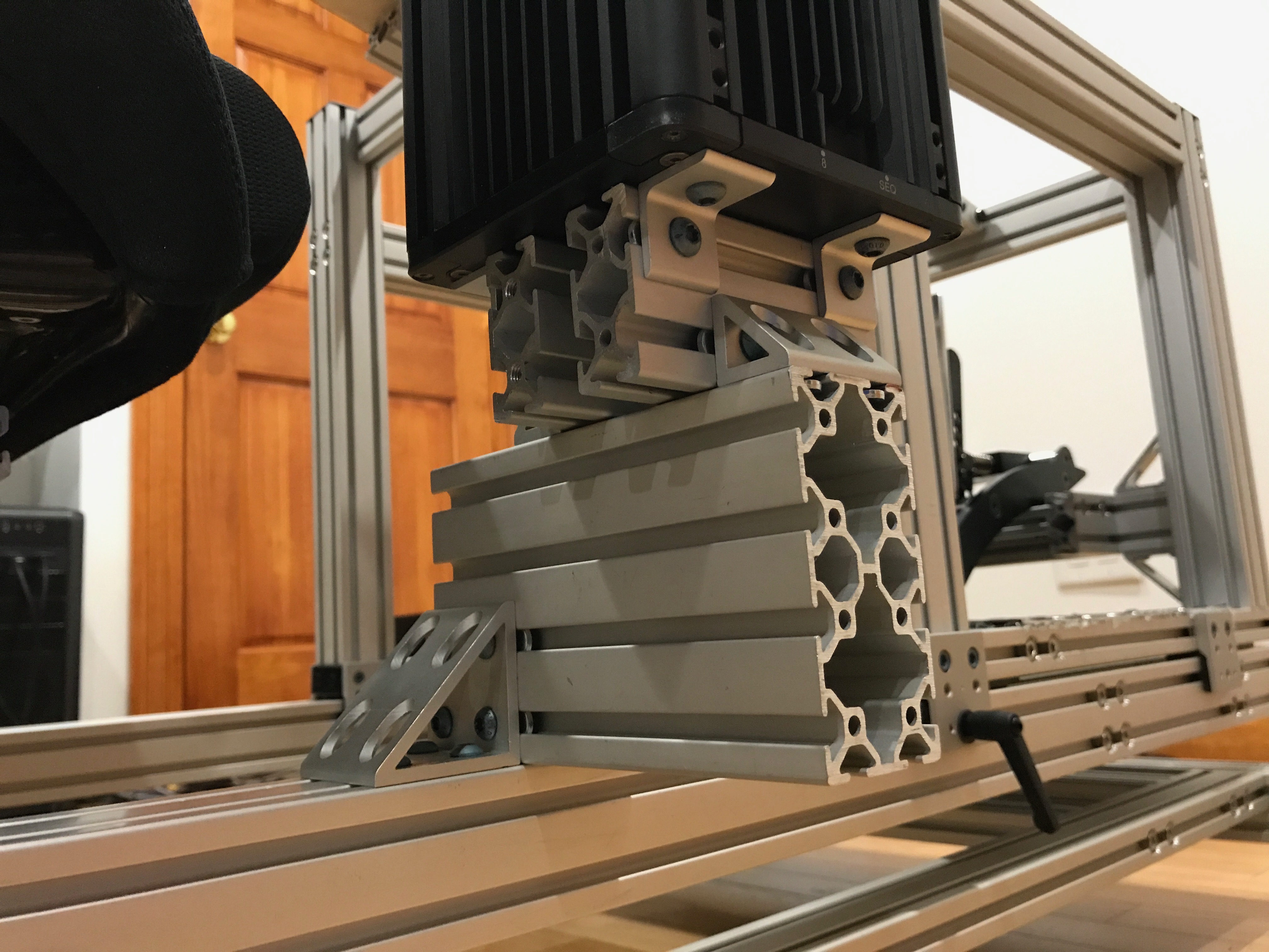\n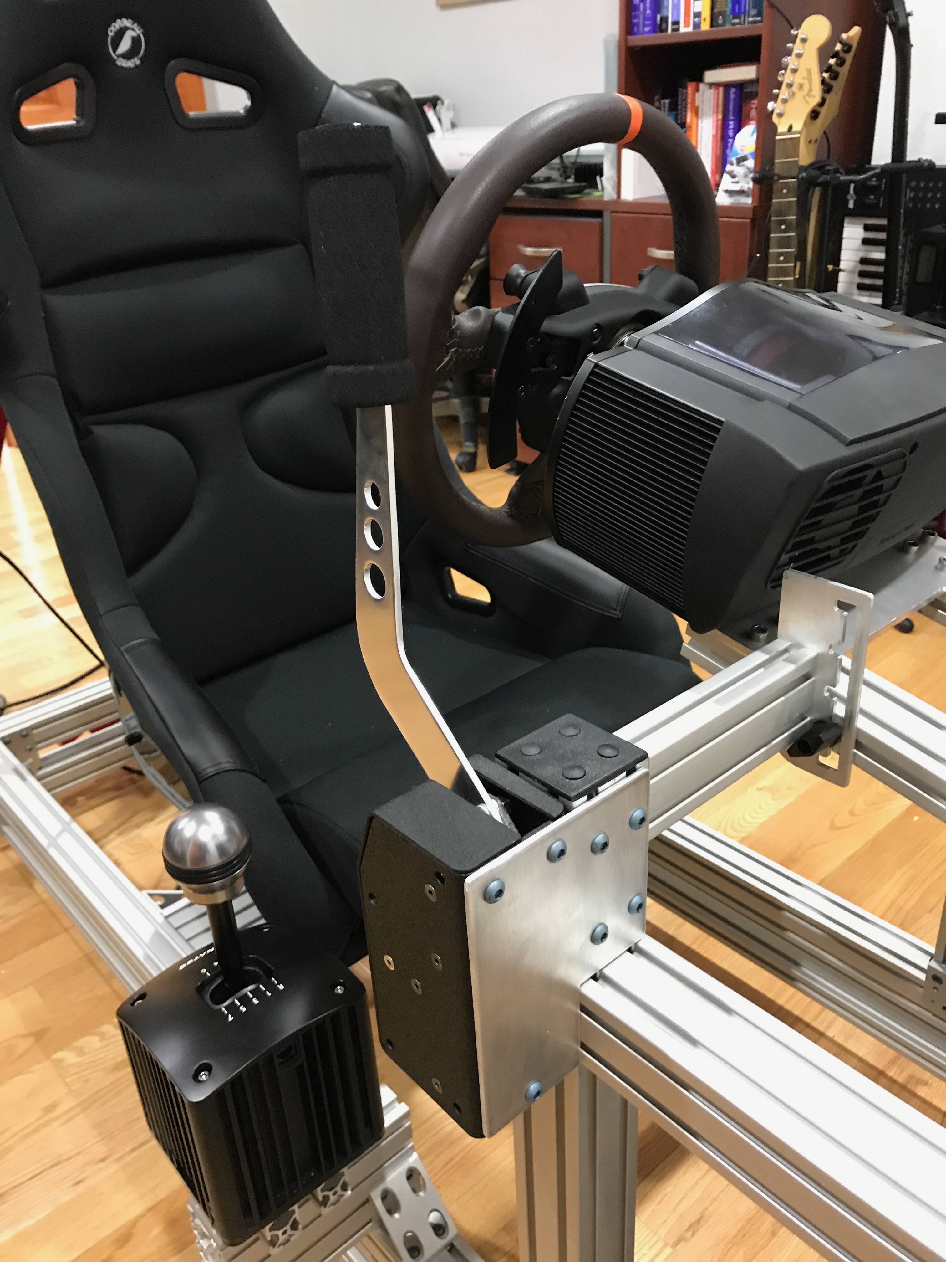\n\nThe transducers mounted directly using 80/20 components.\n\n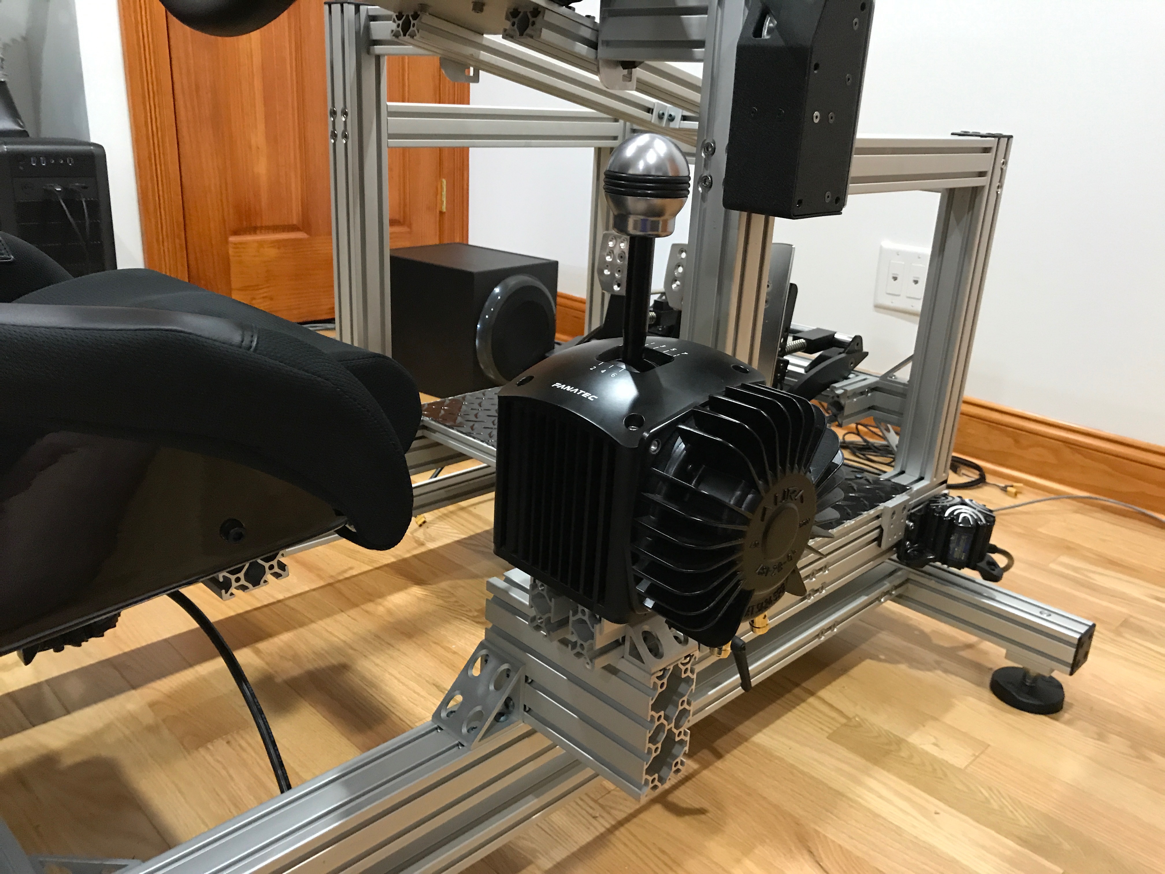\n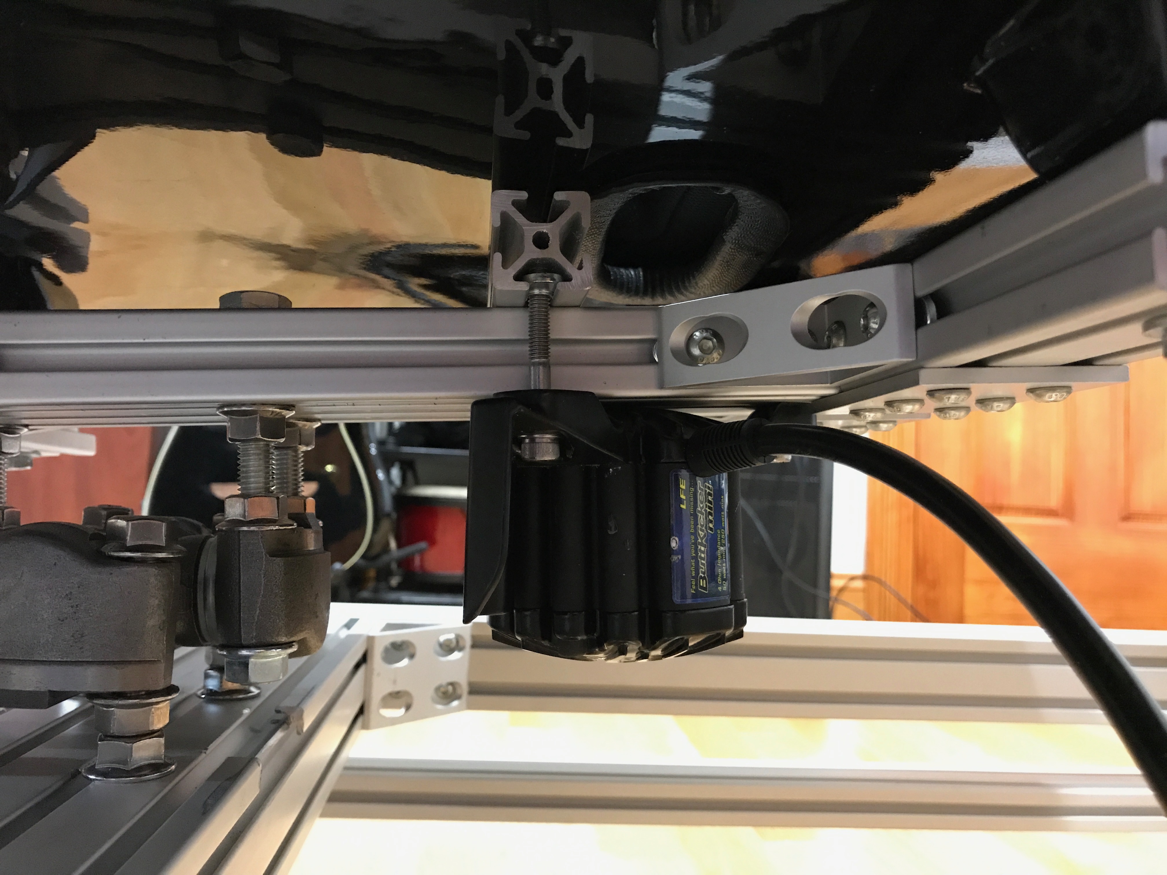\n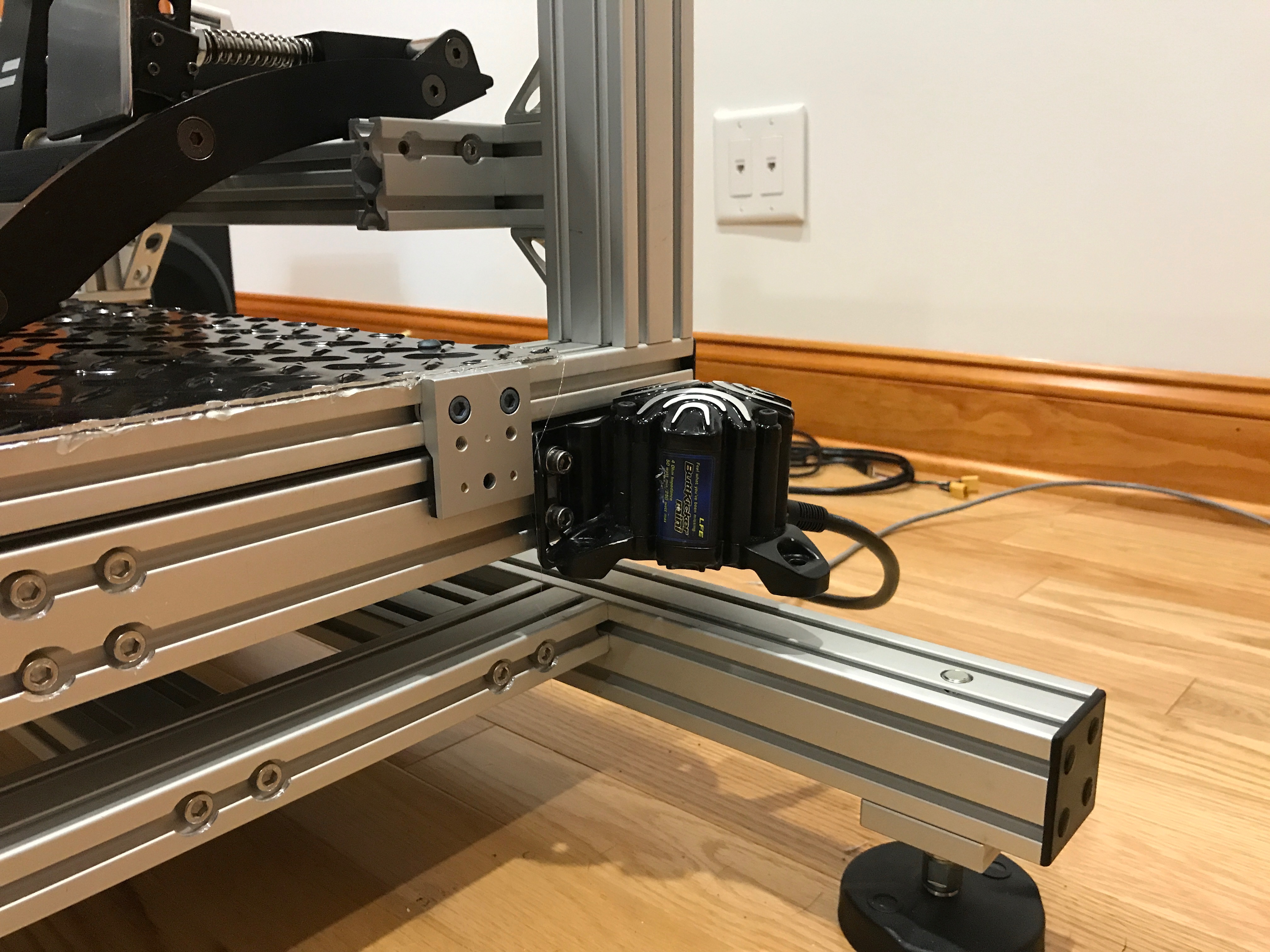\n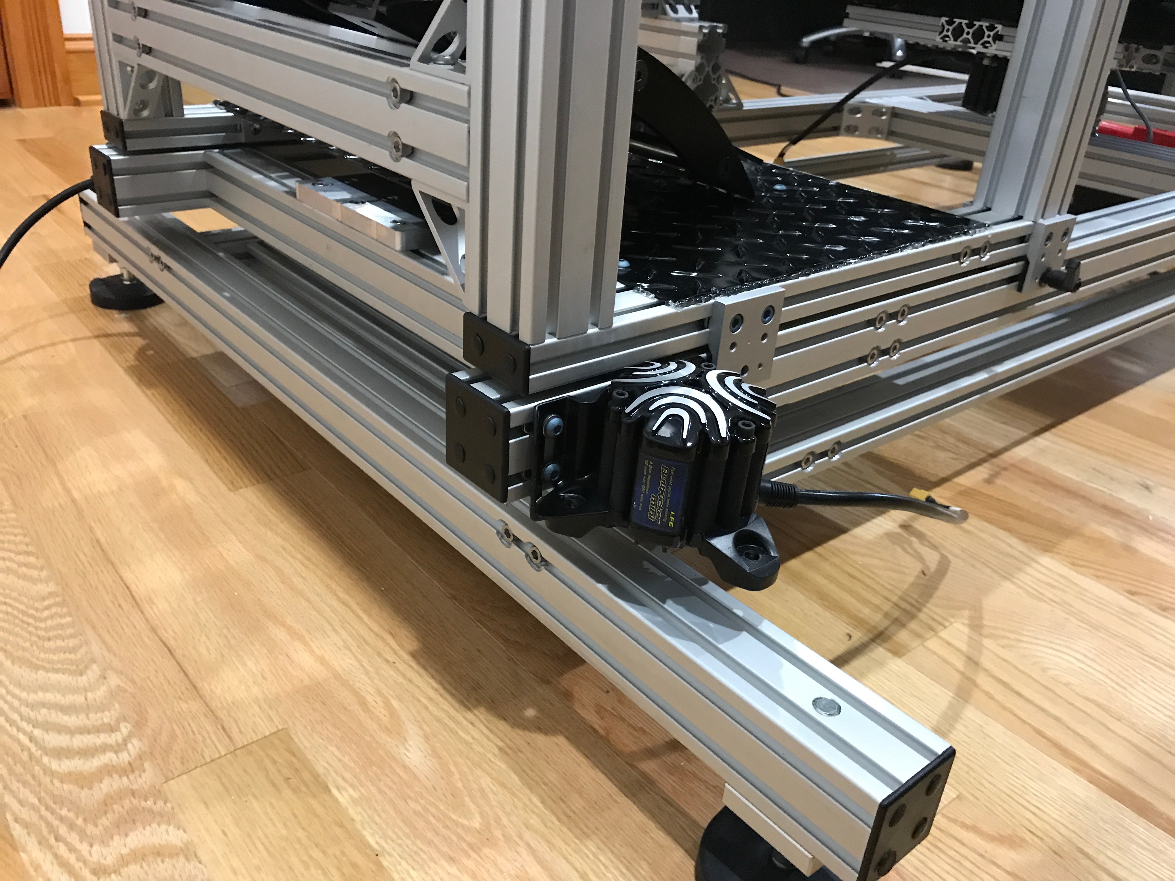\n\nThe final finishing parts came in from [80/20 Inc](https://8020.net): some HDPE for the backend to roll on, plastic end caps, and cable management mounts. I had to make a few minor adjustments to things, but in the end it all came together nicely!\n\n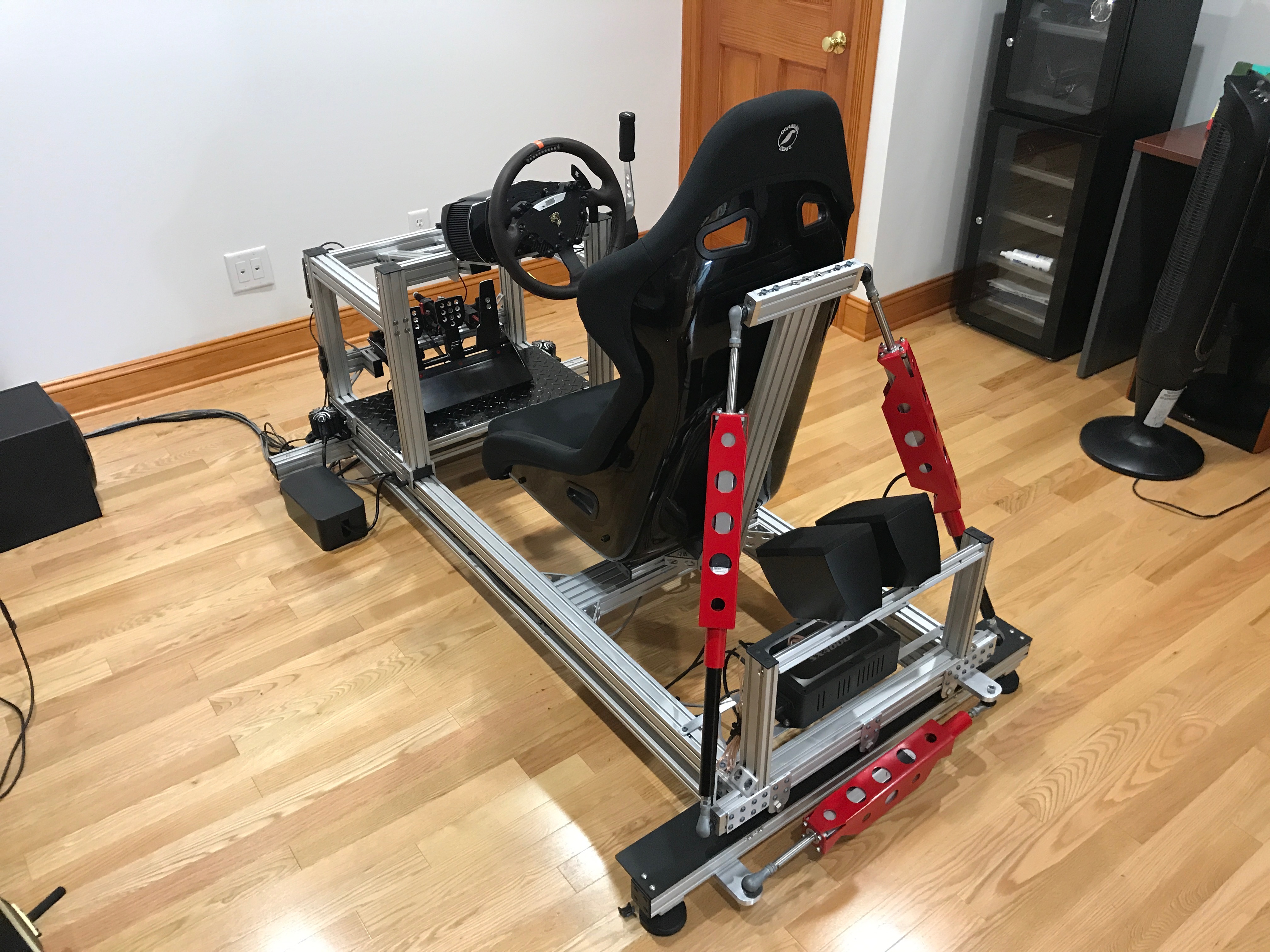\n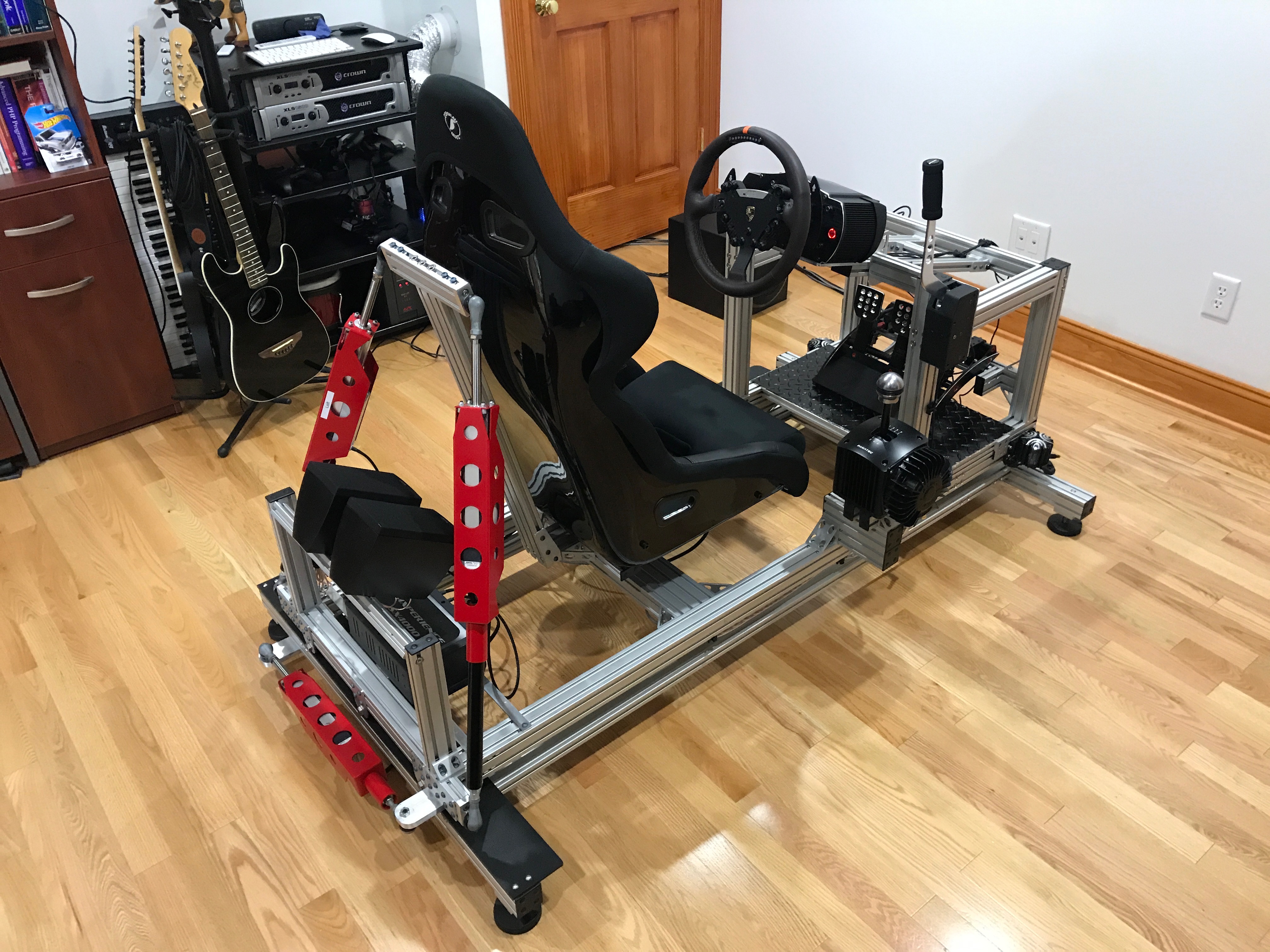\n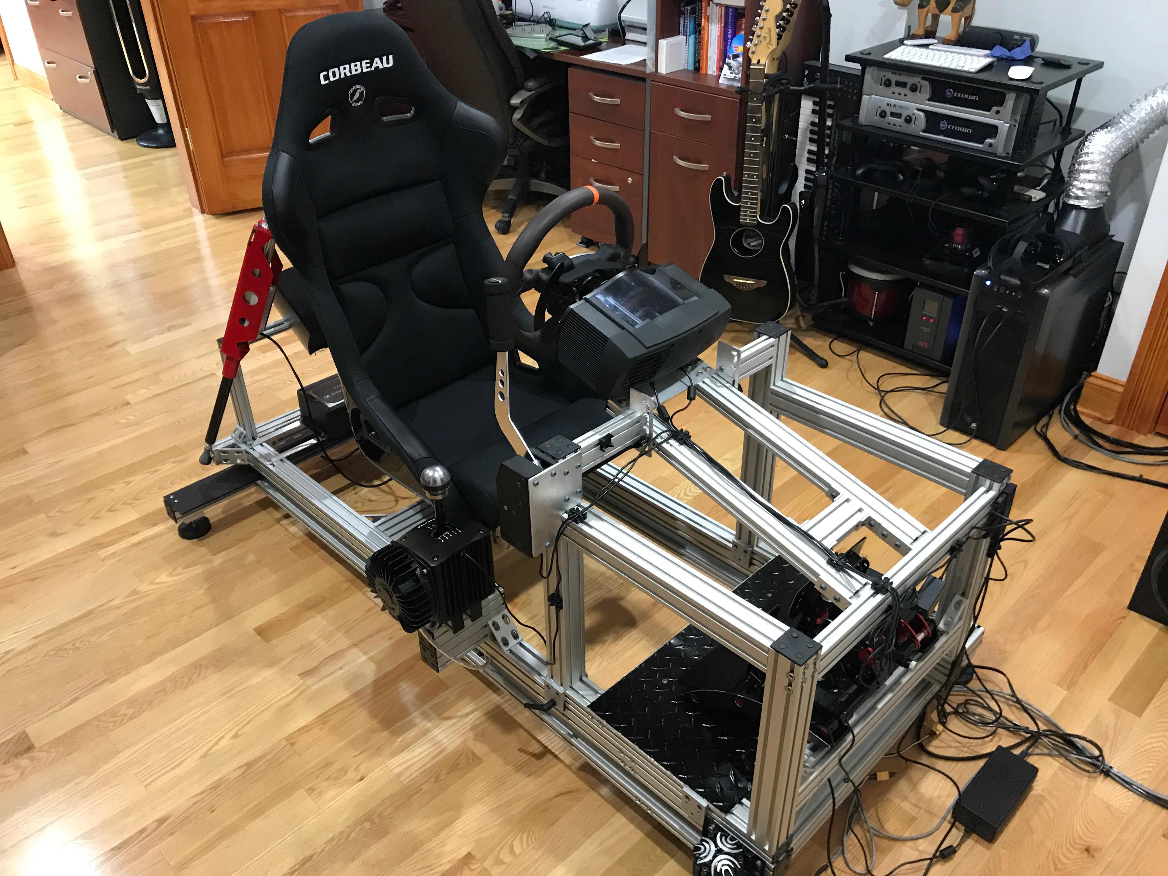\n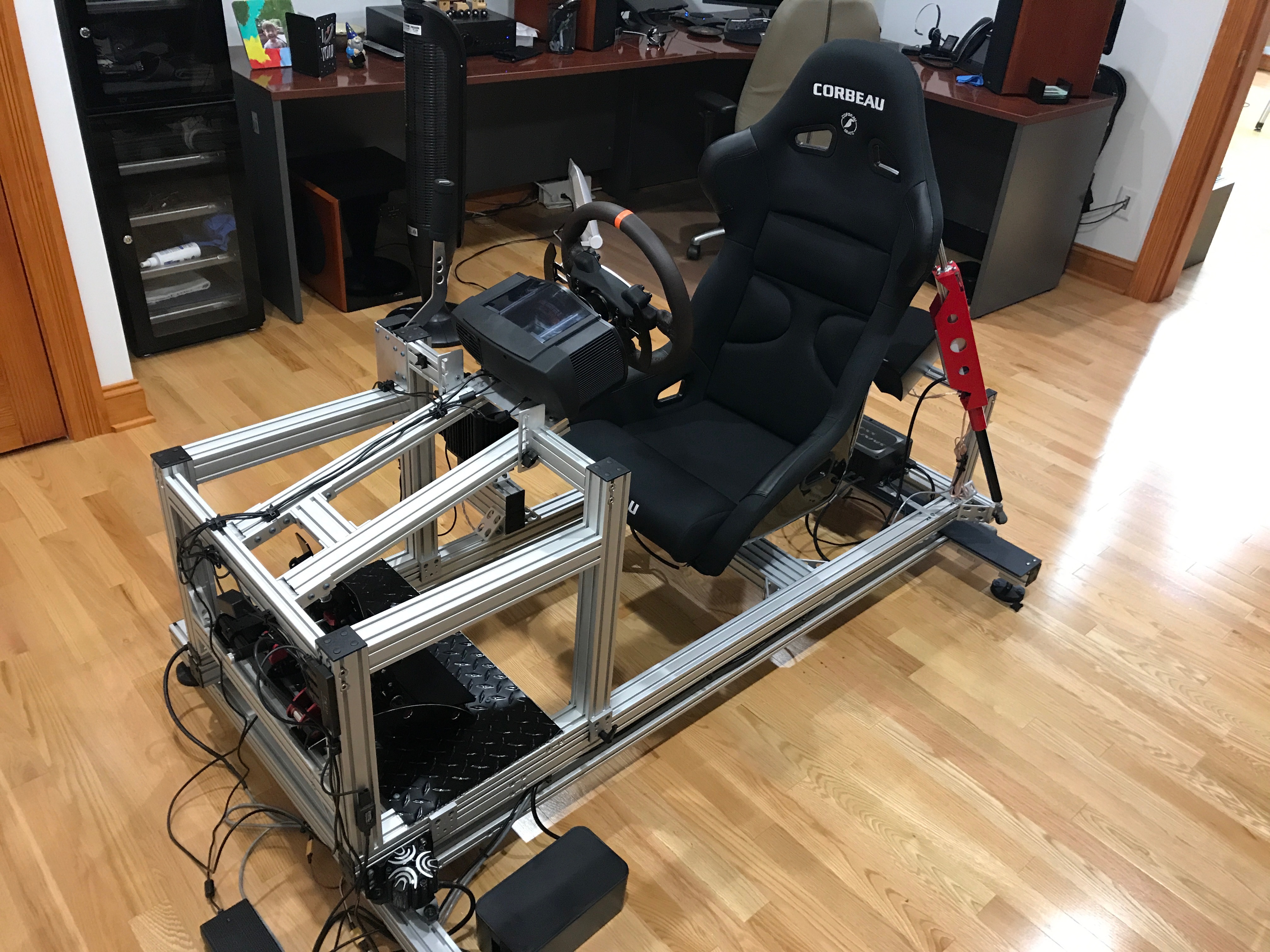\n\n\nHere is the first video of the new rig in action. This is me playing Assetto Corsa in VR.\n\n\u003ciframe width=\"560\" height=\"315\" src=\"https://www.youtube.com/embed/-HftO5CsJCQ\" frameborder=\"0\" allowfullscreen\u003e\u003c/iframe\u003e\n\n\n----\n\n#### Update 6/25/2017: 4 point racing harness.\n\n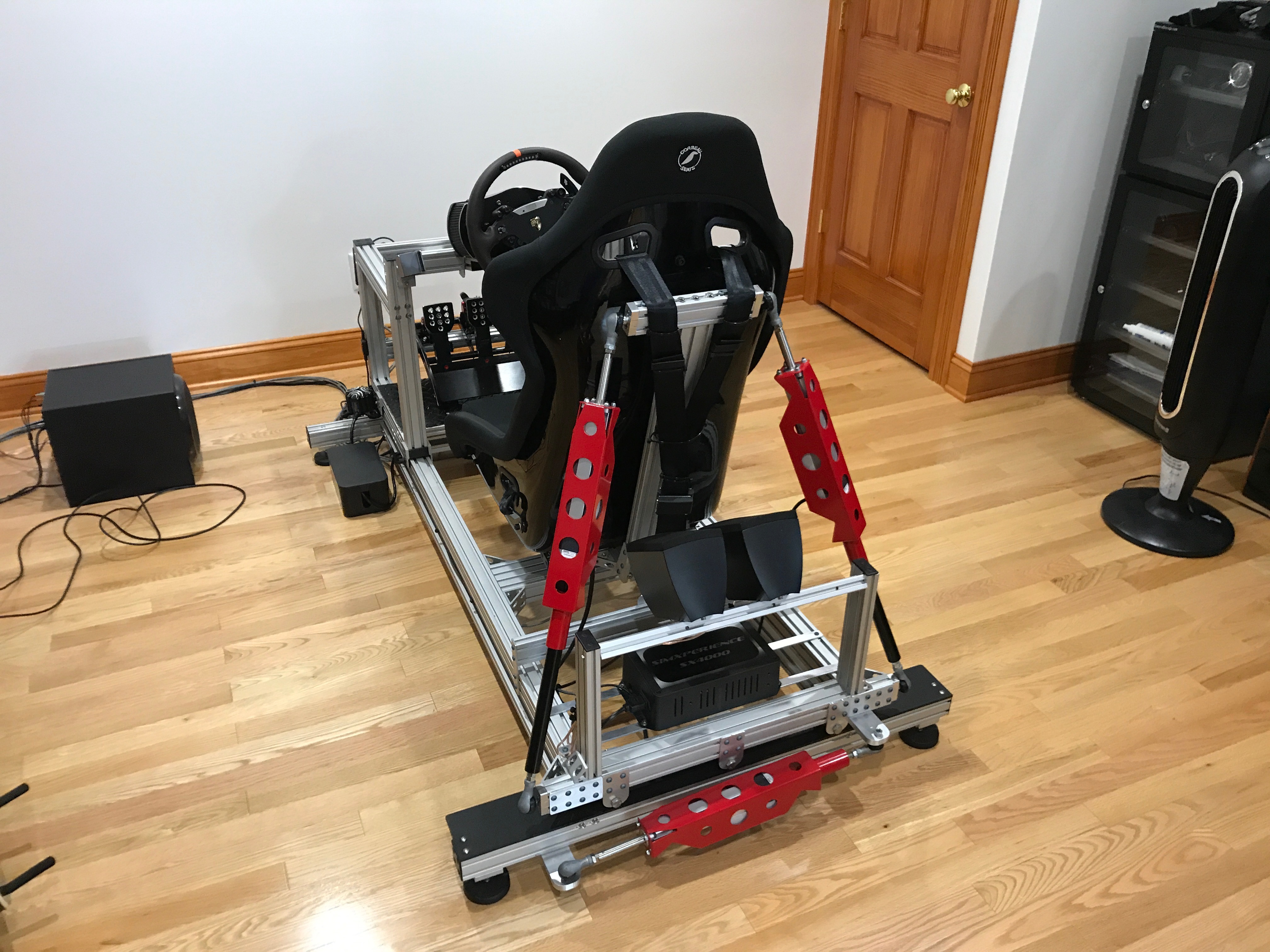\n\nI decided that I needed a racing harness to add to the realism in VR. The harness is mounted to the mid frame with some spring tensioning. When you brake, the seat moves forward, but the harness stays in place, so you feel as if you are being held back by the harness, as you would in a real car. Its a really great experience.\n\n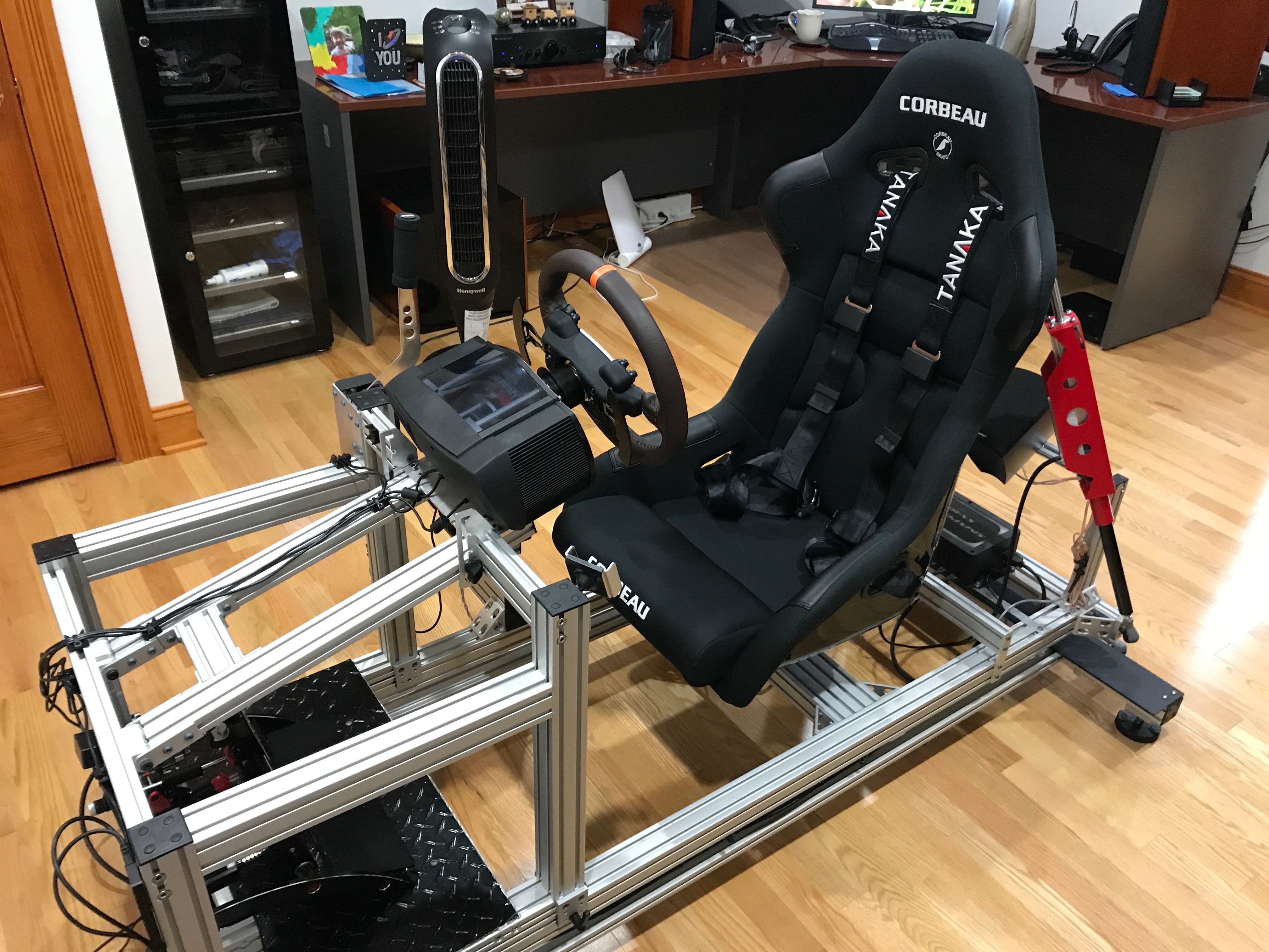\n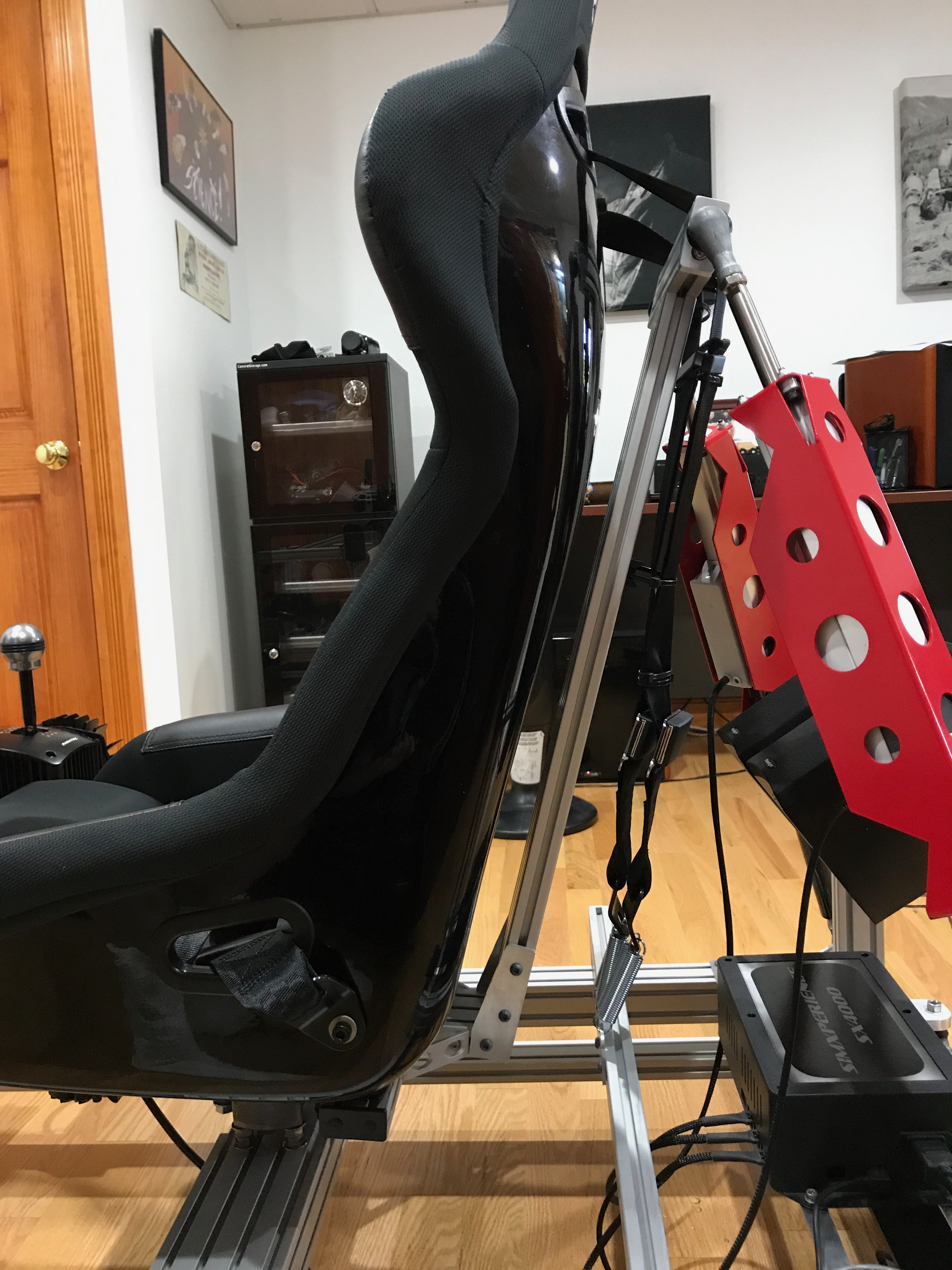\n\nI CNCed a small bracket to mount the springs to the 80/20. The other side of the springs went on to the harness rear mounts, and the harness side mounts went directly on to the seat side brackets.\n\n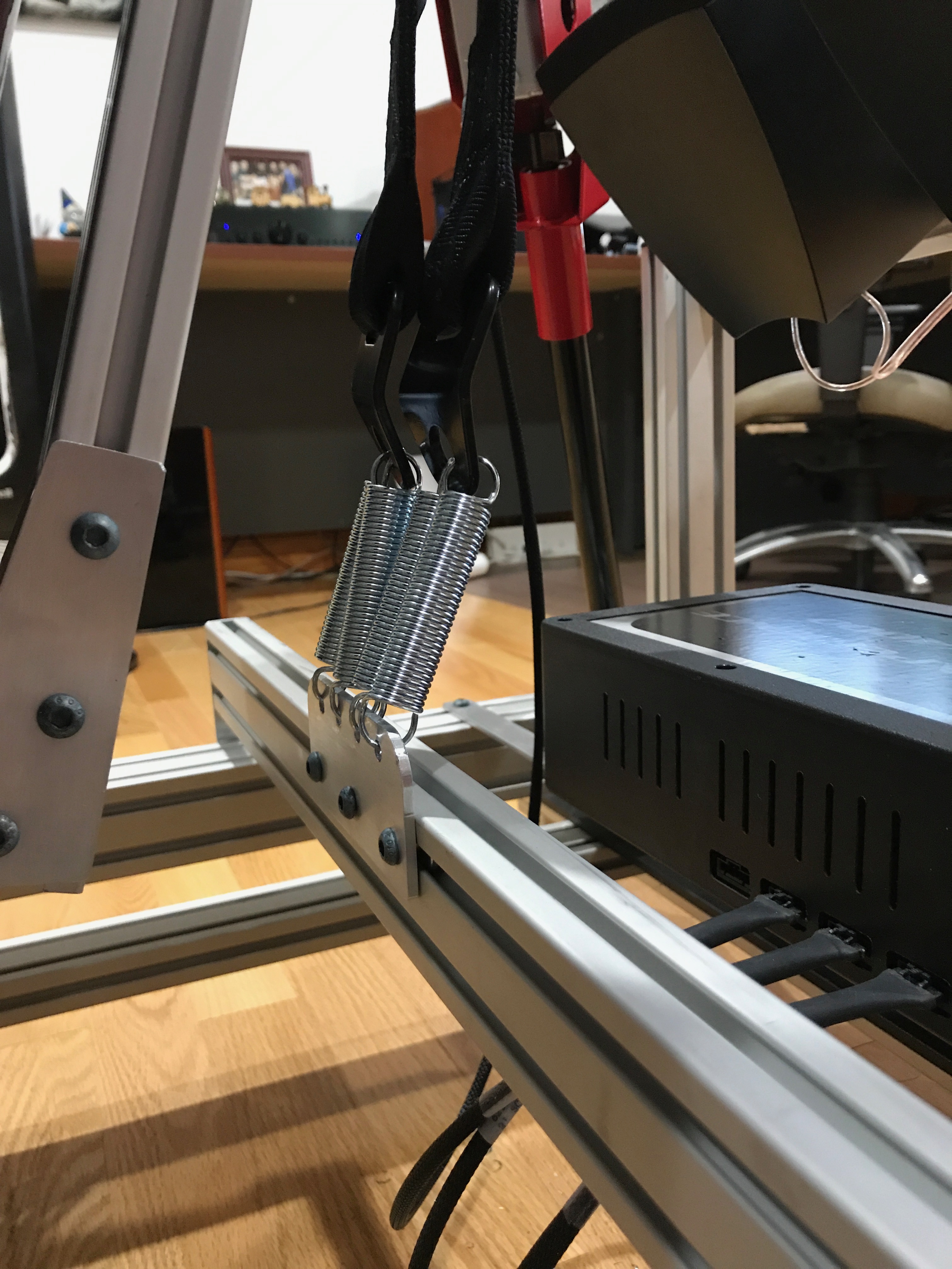","html":"\u003cp\u003eI have really enjoyed having a motion simulator platform for sim racing. It\u0026#39;s fairly close to real world racing, but costs a LOT less money, and there isn\u0026#39;t that risk of serious injury, or death ☠️\u003c/p\u003e\n\u003cp\u003eI started down this path almost 3 years ago, and with the Oculus Rift bringing VR in to the picture, I am truly hooked.\u003c/p\u003e\n\u003cp\u003eVersion 1 of the motion rig was thrown together using 80/20 extrusion that I already had, and it was pieced together without any real planning. One of the biggest drawbacks of version 1 was its inability to easily adjust for other drivers, especially my kids. There were a few other shortcomings: it was uncomfortable, it flexed and squeaked, the rear traction loss wasn\u0026#39;t smooth, the rear speakers flopped around like crazy, and so on...\u003c/p\u003e\n\u003cimg src=\"/content/images/2017/06/IMG_0349.jpg\" alt=\"\"\u003e\n\u003cp\u003eI decided to spend a little while thinking about how to best resolve the big issues, and turned to Fusion360 to design a quick mockup of the main features.\u003c/p\u003e\n\u003cp align=\"center\"\u003e\n\u003cimg src=\"/content/images/2017/06/IMG_0607.JPG\" alt=\"\"\u003e\n\u003c/p\u003e\n\u003cp\u003eThe new design became the basis of what I ordered from \u003ca href=\"https://8020.net\" rel=\"nofollow\"\u003e80/20 Inc\u003c/a\u003e: Extrusion, linear movement components for the sliding top frame, and the hinges for the steering bracket.\u003c/p\u003e\n\u003cp\u003eOnce the extrusion arrived, I quickly mocked up how everything would fit together and came up with an implementation plan.\u003c/p\u003e\n\u003cimg src=\"/content/images/2017/06/IMG_0855.jpg\" alt=\"\"\u003e\n\u003cimg src=\"/content/images/2017/06/IMG_0856.jpg\" alt=\"\"\u003e\n\u003cp\u003eStarting with the lower frame, I came up with a process of thread tapping, drilling, and milling to piece everything together.\u003c/p\u003e\n\u003cimg src=\"/content/images/2017/06/IMG_0876.JPG\" alt=\"\"\u003e\n\u003cimg src=\"/content/images/2017/06/IMG_0877.jpg\" alt=\"\"\u003e\n\u003cp\u003eUsing a mill bit in my drill press, I was able to notch out the recesses so that the bolt heads sat flush to the edge of the extrusion.\u003c/p\u003e\n\u003cimg src=\"/content/images/2017/06/IMG_0881.jpg\" alt=\"\"\u003e\n\u003cimg src=\"/content/images/2017/06/IMG_0880.jpg\" alt=\"\"\u003e\n\u003cp\u003eThis worked out nicely, although my drill press was a little too loose to provide the most accurate cutting. The drill shaft moved all over the place, leaving some of the recesses a little out of alignment.\u003c/p\u003e\n\u003cp\u003eNext was building the mid frame joint. The lower and mid frames were attached together using a GM wheel hub that I picked up on eBay for $20 shipped.\u003c/p\u003e\n\u003cimg src=\"/content/images/2017/06/IMG_0879.jpg\" alt=\"\"\u003e\n\u003cimg src=\"/content/images/2017/06/IMG_0886.jpg\" alt=\"\"\u003e\n\u003cp\u003eI designed this in Fusion360 and milled it using the CNC that I built.\u003c/p\u003e\n\u003cimg src=\"/content/images/2017/06/IMG_0888.JPG\" alt=\"\"\u003e\n\u003cimg src=\"/content/images/2017/06/IMG_0890.jpg\" alt=\"\"\u003e\n\u003cimg src=\"/content/images/2017/06/IMG_0891.JPG\" alt=\"\"\u003e\n\u003cp\u003eOnce that was done, I was able to thread tap the extrusion for the mid frame and pre-assemble it.\u003c/p\u003e\n\u003cimg src=\"/content/images/2017/06/IMG_0892.jpg\" alt=\"\"\u003e\n\u003cimg src=\"/content/images/2017/06/IMG_0894.jpg\" alt=\"\"\u003e\n\u003cp\u003eI then attached this section of the mid frame to the lower frame. I used long threaded bolts so that I could adjust the height that the mid frame sat on the lower frame.\u003c/p\u003e\n\u003cimg src=\"/content/images/2017/06/IMG_0895.jpg\" alt=\"\"\u003e\n\u003cimg src=\"/content/images/2017/06/IMG_0897.jpg\" alt=\"\"\u003e\n\u003cimg src=\"/content/images/2017/06/IMG_0900.jpg\" alt=\"\"\u003e\n\u003cimg src=\"/content/images/2017/06/IMG_0902.jpg\" alt=\"\"\u003e\n\u003cimg src=\"/content/images/2017/06/IMG_0903.jpg\" alt=\"\"\u003e\n\u003cp\u003eThe top frame was then mocked up. The top frame sits on linear sliders to allow it to slide back and forward. This was the biggest improvement over version 1.\u003c/p\u003e\n\u003cimg src=\"/content/images/2017/06/IMG_0912.jpg\" alt=\"\"\u003e\n\u003cimg src=\"/content/images/2017/06/IMG_0917.jpg\" alt=\"\"\u003e\n\u003cp\u003eThere was a lot of drilling and thread tapping to get all the pieces of the top frame together.\u003c/p\u003e\n\u003cimg src=\"/content/images/2017/06/IMG_0920.jpg\" alt=\"\"\u003e\n\u003cimg src=\"/content/images/2017/06/IMG_0930.jpg\" alt=\"\"\u003e\n\u003cimg src=\"/content/images/2017/06/IMG_0931.jpg\" alt=\"\"\u003e\n\u003cimg src=\"/content/images/2017/06/IMG_0936.jpg\" alt=\"\"\u003e\n\u003cp\u003eI pieced together a seat mount using 80/20, rather than using the SimXperience DIY seat kit that I had for version 1. I did this so that I could get the seat sitting lower in the frame.\u003c/p\u003e\n\u003cimg src=\"/content/images/2017/06/IMG_0941.jpg\" alt=\"\"\u003e\n\u003cimg src=\"/content/images/2017/06/IMG_0946.jpg\" alt=\"\"\u003e\n\u003cp\u003eI found a great universal joint on eBay for $30. With this wing style U-Joint, I had a lot more flexibility with how I mounted things. I had to make a quick and dirty jig to get the hole spacing correct as the holes ended up being right along the edge of an extrusion.\u003c/p\u003e\n\u003cimg src=\"/content/images/2017/06/IMG_0944.jpg\" alt=\"\"\u003e\n\u003cimg src=\"/content/images/2017/06/IMG_0947.jpg\" alt=\"\"\u003e\n\u003cimg src=\"/content/images/2017/06/IMG_0949.jpg\" alt=\"\"\u003e\n\u003cp\u003eI also had to notch out part of the extrusion on the mid frame to allow the U-Joint bolts to sit down further at the extreme angles.\u003c/p\u003e\n\u003cimg src=\"/content/images/2017/06/IMG_0950.jpg\" alt=\"\"\u003e\n\u003cimg src=\"/content/images/2017/06/IMG_0951.jpg\" alt=\"\"\u003e\n\u003cimg src=\"/content/images/2017/06/IMG_0952.jpg\" alt=\"\"\u003e\n\u003cimg src=\"/content/images/2017/06/IMG_0953.jpg\" alt=\"\"\u003e\n\u003cp\u003eWith the seat mounted, I then focused on the rear rollers for the traction loss mechanism. These rollers ultimately set the height of the mid frame from the lower frame. I designed the brackets in Fusion360 and milled them on my CNC.\u003c/p\u003e\n\u003cimg src=\"/content/images/2017/06/IMG_0988.jpg\" alt=\"\"\u003e\n\u003cp\u003eI used track rollers that I found on eBay. They were called LR200NPPU Track Roller Double Row Bearing Sealed 10x32x9 Track Bearings 18165. I got 4 for $20.\u003c/p\u003e\n\u003cimg src=\"/content/images/2017/06/IMG_0986.jpg\" alt=\"\"\u003e\n\u003cimg src=\"/content/images/2017/06/IMG_0992.jpg\" alt=\"\"\u003e\n\u003cimg src=\"/content/images/2017/06/IMG_0993.jpg\" alt=\"\"\u003e\n\u003cimg src=\"/content/images/2017/06/IMG_0994.jpg\" alt=\"\"\u003e\n\u003cp\u003eI then mounted them on the cross member of the mid frame.\u003c/p\u003e\n\u003cimg src=\"/content/images/2017/06/IMG_0995.jpg\" alt=\"\"\u003e\n\u003cimg src=\"/content/images/2017/06/IMG_0996.jpg\" alt=\"\"\u003e\n\u003cimg src=\"/content/images/2017/06/IMG_0997.jpg\" alt=\"\"\u003e\n\u003cp\u003eWith the mid frame leveled, I went back to the seat to mount the actuator mount bracket. This was tricky. I had to notch and drill at an angle in the extrusion (98 degrees).\u003c/p\u003e\n\u003cimg src=\"/content/images/2017/06/IMG_1007.jpg\" alt=\"\"\u003e\n\u003cp\u003eI then designed and fabricated some side support brackets to help relieve the 3 bolts that went into the base extrusion on the seat.\u003c/p\u003e\n\u003cimg src=\"/content/images/2017/06/IMG_1011.jpg\" alt=\"\"\u003e\n\u003cimg src=\"/content/images/2017/06/IMG_1012.jpg\" alt=\"\"\u003e\n\u003cimg src=\"/content/images/2017/06/IMG_1013.jpg\" alt=\"\"\u003e\n\u003cp\u003eI had to design and fabricate end caps for the extrusion that would allow me to thread tap for the actuators. This was the thickest aluminum stock that I had milled on my CNC at the time. Everything went ok-ish... Mid job the x-axis coupler came loose and the CNC started to dig into the piece. I was able to stop it and recover the job without any major damage.\u003c/p\u003e\n\u003cimg src=\"/content/images/2017/06/IMG_1015.jpg\" alt=\"\"\u003e\n\u003cimg src=\"/content/images/2017/06/IMG_1016.jpg\" alt=\"\"\u003e\n\u003cimg src=\"/content/images/2017/06/IMG_1020.jpg\" alt=\"\"\u003e\n\u003cimg src=\"/content/images/2017/06/IMG_1023.jpg\" alt=\"\"\u003e\n\u003cimg src=\"/content/images/2017/06/IMG_1027.jpg\" alt=\"\"\u003e\n\u003cimg src=\"/content/images/2017/06/IMG_1028.jpg\" alt=\"\"\u003e\n\u003cimg src=\"/content/images/2017/06/IMG_1029.jpg\" alt=\"\"\u003e\n\u003cimg src=\"/content/images/2017/06/IMG_1032.jpg\" alt=\"\"\u003e\n\u003cimg src=\"/content/images/2017/06/IMG_1033.jpg\" alt=\"\"\u003e\n\u003cimg src=\"/content/images/2017/06/IMG_1034.jpg\" alt=\"\"\u003e\n\u003cimg src=\"/content/images/2017/06/IMG_1035.jpg\" alt=\"\"\u003e\n\u003cp\u003eThe rear traction loss actuator needed a pair of brackets. Again, designed in Fusion360, then milled on my CNC.\u003c/p\u003e\n\u003cp align=\"center\"\u003e\n\u003cimg src=\"/content/images/2017/06/IMG_1044.JPG\" alt=\"\"\u003e\n\u003c/p\u003e\n\u003cimg src=\"/content/images/2017/06/IMG_1049.jpg\" alt=\"\"\u003e\n\u003cimg src=\"/content/images/2017/06/IMG_1046.jpg\" alt=\"\"\u003e\n\u003cimg src=\"/content/images/2017/06/IMG_1051.jpg\" alt=\"\"\u003e\n\u003cimg src=\"/content/images/2017/06/IMG_1052.jpg\" alt=\"\"\u003e\n\u003cimg src=\"/content/images/2017/06/IMG_1053.jpg\" alt=\"\"\u003e\n\u003cp\u003eI marked and drilled out the mounting plate for the steering wheel. This was just a piece of stock that I purchased from \u003ca href=\"https://8020.net\" rel=\"nofollow\"\u003e80/20 Inc\u003c/a\u003e.\u003c/p\u003e\n\u003cimg src=\"/content/images/2017/06/IMG_1037.jpg\" alt=\"\"\u003e\n\u003cp\u003eThen designed and milled the brackets for the steering height adjustment.\u003c/p\u003e\n\u003cimg src=\"/content/images/2017/06/IMG_1055.jpg\" alt=\"\"\u003e\n\u003cimg src=\"/content/images/2017/06/IMG_1056.jpg\" alt=\"\"\u003e\n\u003cimg src=\"/content/images/2017/06/IMG_1060.jpg\" alt=\"\"\u003e\n\u003cimg src=\"/content/images/2017/06/IMG_1061.jpg\" alt=\"\"\u003e\n\u003cp\u003eMounting the shifter and handbrake was pretty straight forward. I was able to use 80/20 components for the shifter and I re-used the version 1 handbrake mount with slight modification.\u003c/p\u003e\n\u003cimg src=\"/content/images/2017/06/IMG_1075.jpg\" alt=\"\"\u003e\n\u003cimg src=\"/content/images/2017/06/IMG_1076.jpg\" alt=\"\"\u003e\n\u003cimg src=\"/content/images/2017/06/IMG_1077.jpg\" alt=\"\"\u003e\n\u003cimg src=\"/content/images/2017/06/IMG_1079.jpg\" alt=\"\"\u003e\n\u003cp\u003eThe transducers mounted directly using 80/20 components.\u003c/p\u003e\n\u003cimg src=\"/content/images/2017/06/IMG_1080.jpg\" alt=\"\"\u003e\n\u003cimg src=\"/content/images/2017/06/IMG_1081.jpg\" alt=\"\"\u003e\n\u003cimg src=\"/content/images/2017/06/IMG_1082.jpg\" alt=\"\"\u003e\n\u003cimg src=\"/content/images/2017/06/IMG_1083.jpg\" alt=\"\"\u003e\n\u003cp\u003eThe final finishing parts came in from \u003ca href=\"https://8020.net\" rel=\"nofollow\"\u003e80/20 Inc\u003c/a\u003e: some HDPE for the backend to roll on, plastic end caps, and cable management mounts. I had to make a few minor adjustments to things, but in the end it all came together nicely!\u003c/p\u003e\n\u003cimg src=\"/content/images/2017/06/IMG_1135.jpg\" alt=\"\"\u003e\n\u003cimg src=\"/content/images/2017/06/IMG_1136-1.jpg\" alt=\"\"\u003e\n\u003cimg src=\"/content/images/2017/06/IMG_1137.jpg\" alt=\"\"\u003e\n\u003cimg src=\"/content/images/2017/06/IMG_1138.jpg\" alt=\"\"\u003e\n\u003cp\u003eHere is the first video of the new rig in action. This is me playing Assetto Corsa in VR.\u003c/p\u003e\n\u003ciframe width=\"560\" height=\"315\" src=\"https://www.youtube.com/embed/-HftO5CsJCQ\" frameborder=\"0\" allowfullscreen=\"\"\u003e\u003c/iframe\u003e\n\u003chr\u003e\n\u003ch4\u003eUpdate 6/25/2017: 4 point racing harness.\u003c/h4\u003e\n\u003cimg src=\"/content/images/2017/06/IMG_1243.jpg\" alt=\"\"\u003e\n\u003cp\u003eI decided that I needed a racing harness to add to the realism in VR. The harness is mounted to the mid frame with some spring tensioning. When you brake, the seat moves forward, but the harness stays in place, so you feel as if you are being held back by the harness, as you would in a real car. Its a really great experience.\u003c/p\u003e\n\u003cimg src=\"/content/images/2017/06/IMG_1244.jpg\" alt=\"\"\u003e\n\u003cimg src=\"/content/images/2017/06/IMG_1247.jpg\" alt=\"\"\u003e\n\u003cp\u003eI CNCed a small bracket to mount the springs to the 80/20. The other side of the springs went on to the harness rear mounts, and the harness side mounts went directly on to the seat side brackets.\u003c/p\u003e\n\u003cimg src=\"/content/images/2017/06/IMG_1246.jpg\" alt=\"\"\u003e","excerpt":"","metaTitle":"","metaDescription":"","status":"published","featured":false,"publishedAt":"2017-06-19T17:18:00Z","authorId":"190160de54f2192bd5b8734ec8808086","authorName":"Daniel Chote","authorSlug":"daniel","heroMediaId":"11d29d0c27b5c5d2beab0028e2225574","projectId":"","tags":[{"id":"ecaaace3f367d1a9865ae0933d53d715","name":"Sim Racing","slug":"sim-racing"},{"id":"9c4230a56ffd914aade79798824d9d23","name":"SimXperience","slug":"simxperience"},{"id":"ab4bc19e35909615ae7bc6a344a2b50a","name":"Motion Simulator","slug":"motion-simulator"},{"id":"2a3f03a7e12b72da604fe14c788b2d6a","name":"Oculus Rift","slug":"oculus-rift"},{"id":"928d2c45771da339c0d53b265eb1000f","name":"Assetto Corsa","slug":"assetto-corsa"},{"id":"6c984eeb13d39eab0477f9c4ac9ae137","name":"Fanatec","slug":"fanatec"},{"id":"6c42680dd910bc849c96e14d4af5b659","name":"Transducer","slug":"transducer"}],"createdAt":"2026-10-18T13:16:27Z","updatedAt":"2026-10-18T13:16:27Z"},{"id":"8060d348c89d6a36c962a8c289b54bab","siteId":"projectable","slug":"entry-in-to-vr-sim-racing","title":"Entry in to VR Sim Racing","markdown":"I am now starting to explore VR Sim Racing with an Oculus Rift! I went with the Rift over the HTC Vive purely out of native support in the games I play.\n\nAfter much headache in upgrading from Windows 7 to Windows 10, getting the Rift working on my system took quite a lot of messing with the sensors on different USB ports. This was a rather frustrating experience, as one of the two sensors would keep going in to error state, but it wasn't obvious as to which sensor that was, so I kept having to unplug both. \n\n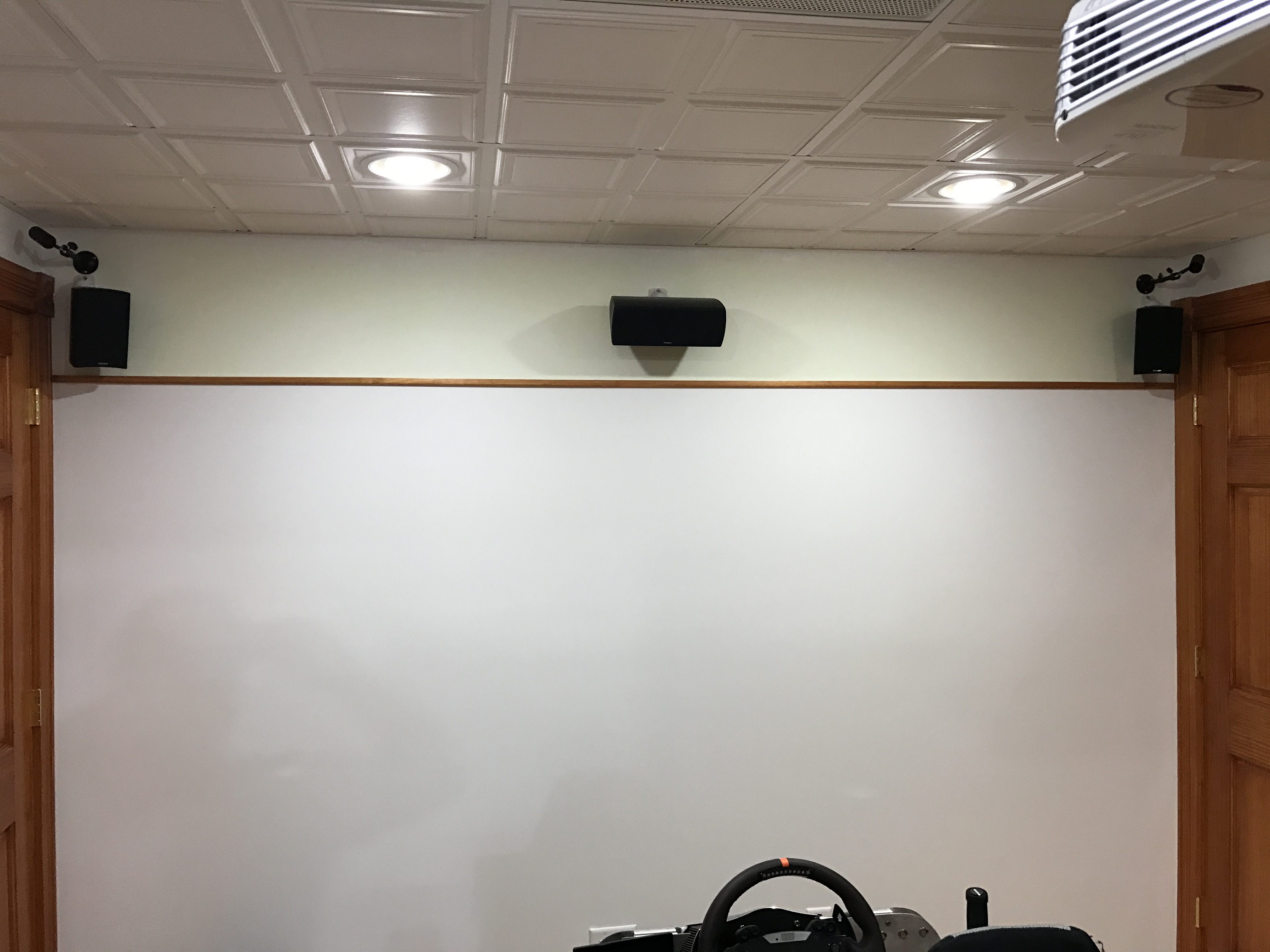\n\nI mounted the sensors above my speakers on the front wall, and ran 15ft active USB extensions for each sensor. \n\n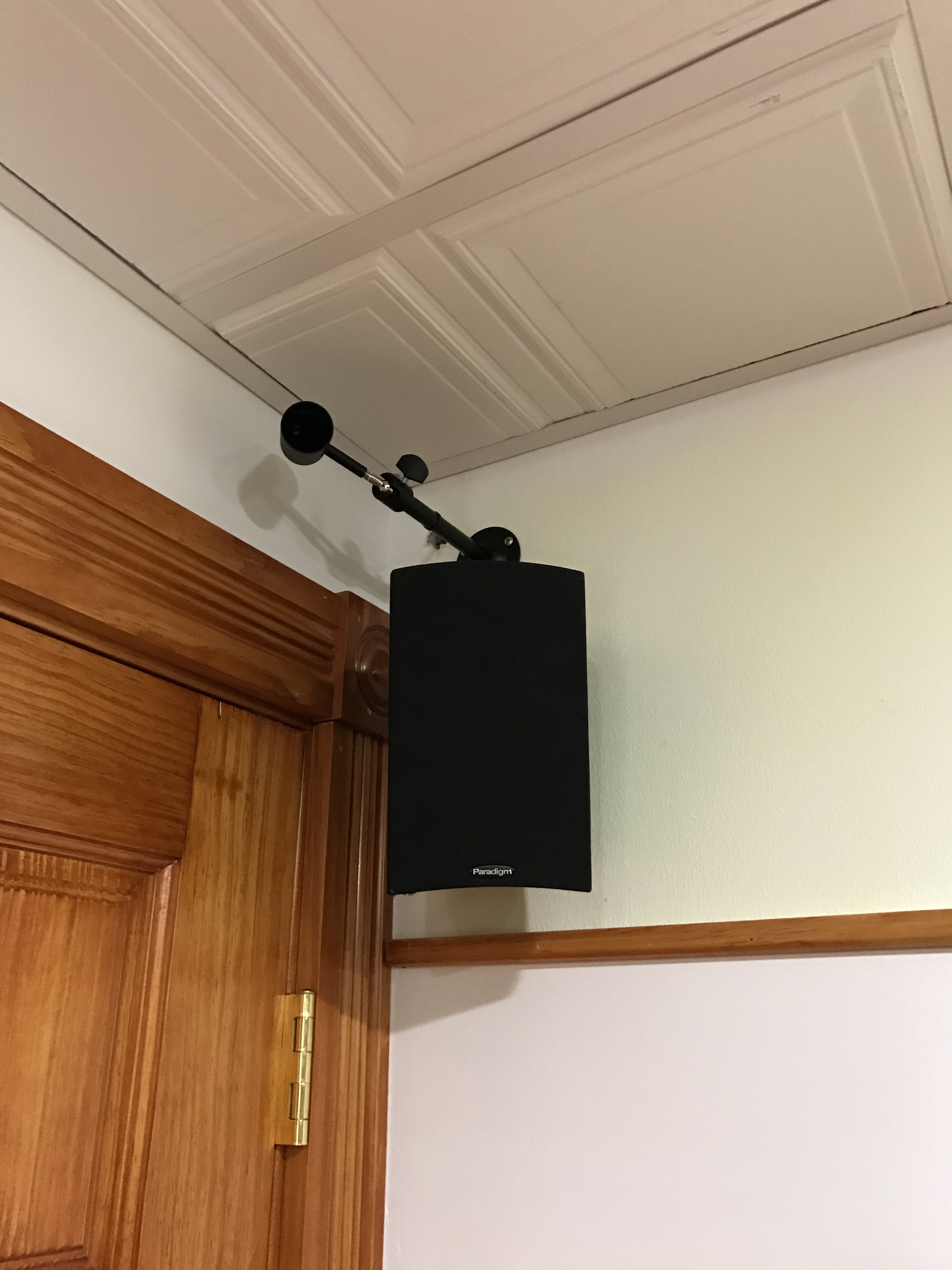\n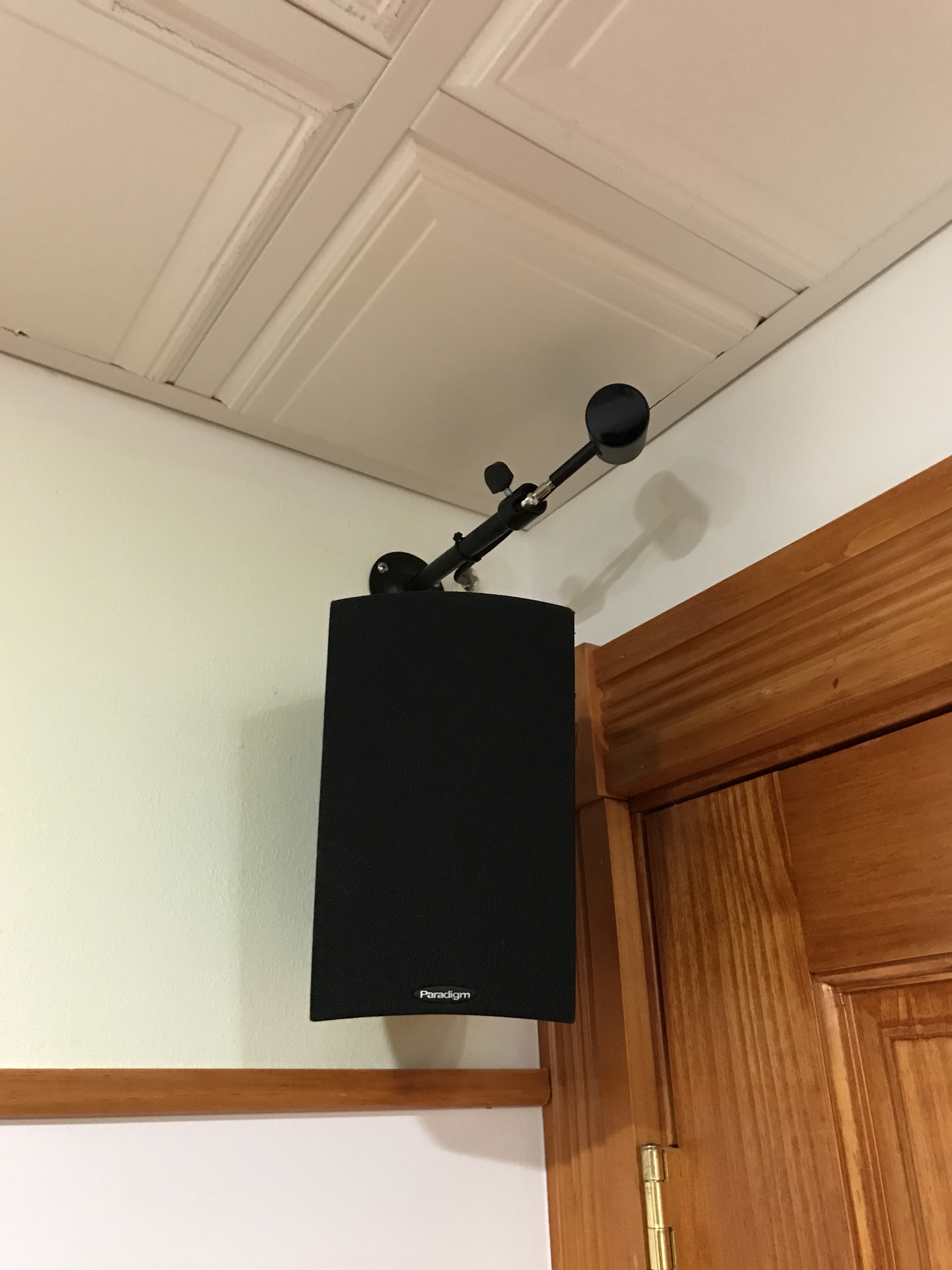\n\nEach sensor is connected to a different USB port group directly on the motherboard. I found that the ASMedia 3.0 ports did not work at all for any of the Rift components.\n\nI eventually got it fairly stable, one of the sensors will occasionally error out with a very unhelpful error message. But it is not a frequent thing.\n\n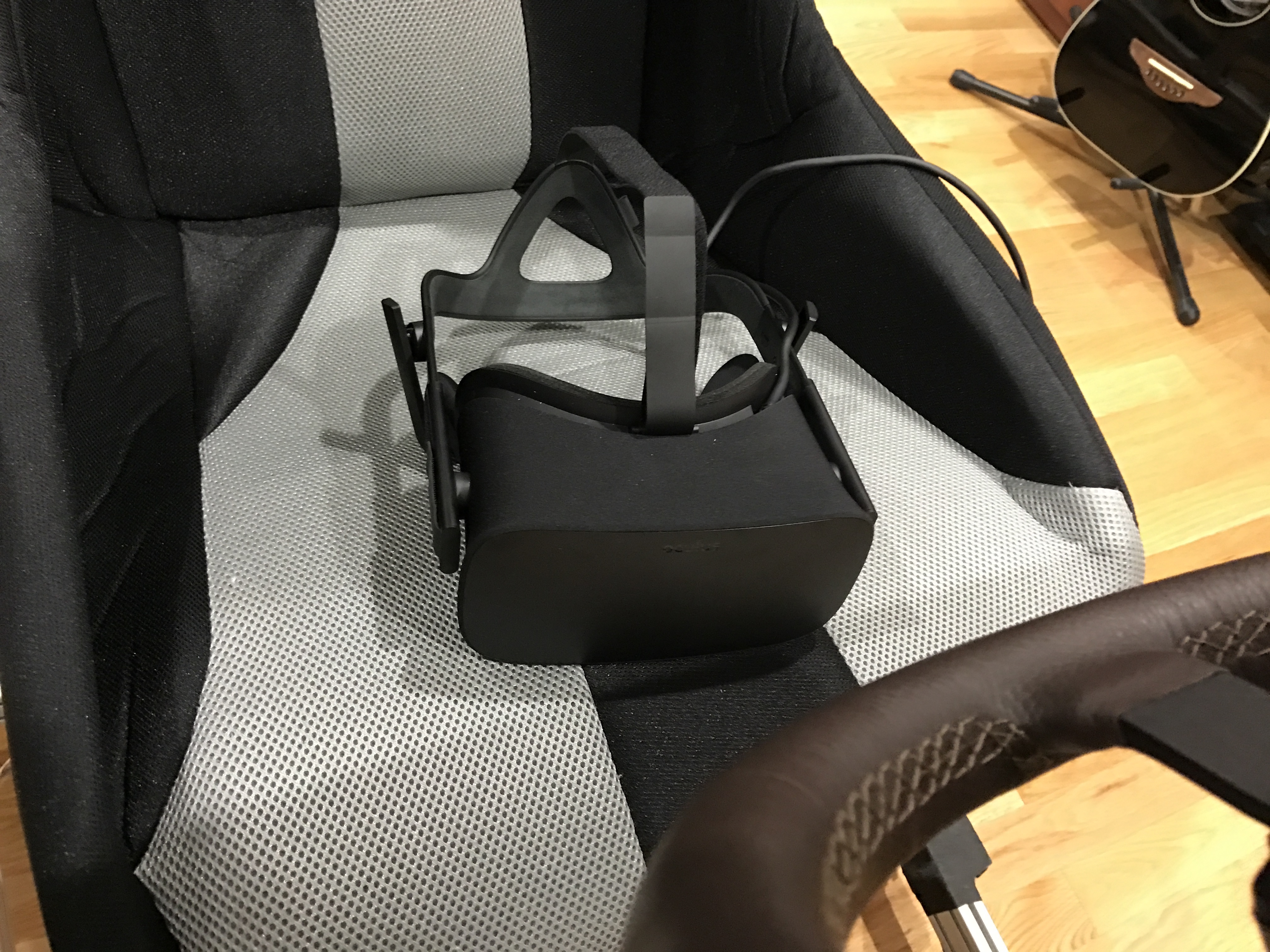\n\nSo far I have only played Assetto Corsa in VR. Its amazingly immersive. Wearing the Rift headset kinda feels like wearing a helmet, and the limited FOV plays in to that helmet feel, making it feel really natural. Being seated also helps with the immersion, you don't have weird room scale issues to deal with.\n\nMy wife attempted driving in VR, she tapped out in less than 2 minutes... She got really nauseous really quickly. I on the other-hand, having the DK1 back in the day, could easily wear the CV1 all day long without any problems.\n\n\u003ciframe width=\"560\" height=\"315\" src=\"https://www.youtube.com/embed/qby0-3SSgtc\" frameborder=\"0\" allowfullscreen\u003e\u003c/iframe\u003e","html":"\u003cp\u003eI am now starting to explore VR Sim Racing with an Oculus Rift! I went with the Rift over the HTC Vive purely out of native support in the games I play.\u003c/p\u003e\n\u003cp\u003eAfter much headache in upgrading from Windows 7 to Windows 10, getting the Rift working on my system took quite a lot of messing with the sensors on different USB ports. This was a rather frustrating experience, as one of the two sensors would keep going in to error state, but it wasn\u0026#39;t obvious as to which sensor that was, so I kept having to unplug both.\u003c/p\u003e\n\u003cimg src=\"/content/images/2017/03/IMG_0374.JPG\" alt=\"\"\u003e\n\u003cp\u003eI mounted the sensors above my speakers on the front wall, and ran 15ft active USB extensions for each sensor.\u003c/p\u003e\n\u003cimg src=\"/content/images/2017/03/IMG_0375-1.JPG\" alt=\"\"\u003e\n\u003cimg src=\"/content/images/2017/03/IMG_0376.JPG\" alt=\"\"\u003e\n\u003cp\u003eEach sensor is connected to a different USB port group directly on the motherboard. I found that the ASMedia 3.0 ports did not work at all for any of the Rift components.\u003c/p\u003e\n\u003cp\u003eI eventually got it fairly stable, one of the sensors will occasionally error out with a very unhelpful error message. But it is not a frequent thing.\u003c/p\u003e\n\u003cimg src=\"/content/images/2017/03/IMG_0377-1.JPG\" alt=\"\"\u003e\n\u003cp\u003eSo far I have only played Assetto Corsa in VR. Its amazingly immersive. Wearing the Rift headset kinda feels like wearing a helmet, and the limited FOV plays in to that helmet feel, making it feel really natural. Being seated also helps with the immersion, you don\u0026#39;t have weird room scale issues to deal with.\u003c/p\u003e\n\u003cp\u003eMy wife attempted driving in VR, she tapped out in less than 2 minutes... She got really nauseous really quickly. I on the other-hand, having the DK1 back in the day, could easily wear the CV1 all day long without any problems.\u003c/p\u003e\n\u003ciframe width=\"560\" height=\"315\" src=\"https://www.youtube.com/embed/qby0-3SSgtc\" frameborder=\"0\" allowfullscreen=\"\"\u003e\u003c/iframe\u003e","excerpt":"","metaTitle":"","metaDescription":"","status":"published","featured":false,"publishedAt":"2017-03-31T14:24:39Z","authorId":"190160de54f2192bd5b8734ec8808086","authorName":"Daniel Chote","authorSlug":"daniel","heroMediaId":"613df49fc3666008f399f82be61dc91c","projectId":"","tags":[{"id":"ecaaace3f367d1a9865ae0933d53d715","name":"Sim Racing","slug":"sim-racing"},{"id":"9c4230a56ffd914aade79798824d9d23","name":"SimXperience","slug":"simxperience"},{"id":"ab4bc19e35909615ae7bc6a344a2b50a","name":"Motion Simulator","slug":"motion-simulator"},{"id":"2a3f03a7e12b72da604fe14c788b2d6a","name":"Oculus Rift","slug":"oculus-rift"},{"id":"928d2c45771da339c0d53b265eb1000f","name":"Assetto Corsa","slug":"assetto-corsa"}],"createdAt":"2026-10-18T13:16:27Z","updatedAt":"2026-10-18T13:16:27Z"}],"site":{"id":"projectable","theme":"projectable","title":"Daniel Chote's Project Blog","description":"Software Development, Hardware Hacking, Sim Racing, Multirotors and Robots!","timezone":"America/New_York","postsPerPage":10,"logoMediaId":"21557257b3f2ecc4b3fa875b808097a7","coverMediaId":"25f1417193daeb2af73861aaa0dd17fd","copyright":"© Daniel Chote","twitterUrl":"https://twitter.com/dchote","linkedinUrl":"https://www.linkedin.com/in/dchote","googleTagId":"G-07GJBQVM38","hosts":[{"host":"new.projectable.me","canonical":false},{"host":"projectable.me","canonical":true},{"host":"www.projectable.me","canonical":false}]},"tag":{"name":"Oculus Rift","slug":"oculus-rift"},"tagId":"2a3f03a7e12b72da604fe14c788b2d6a","total":2}