{"authorId":"","cover":"/content/images/2016/08/IMG_7487.jpg","heroes":{"3b428344cc73fc1bff50ed42b01a17ca":"/content/images/2016/09/IMG_8992.JPG","5c6c6c8242f9d3e5e6550eef9bddccaf":"/content/images/2016/08/IMG_8842.JPG","72b96875d26f256ca5a8e7bea23a0319":"/content/images/2017/07/logo.png","901f2fab2646e83671fe8f6e5500c117":"/content/images/2018/11/IMG_6734.jpg","94b2de371382ec793a64ed49343c14c6":"/content/images/2017/11/IMG_3194.JPG"},"kind":"tag","logo":"/content/images/2016/08/projectable-me-4.png","nav":[{"id":"62e854d471683dea63488bcbca5c6188","label":"Home","url":"/","sortOrder":0},{"id":"1bc84fb15620acd635df7735a0b8ddd8","label":"Raspberry Pi","url":"/tag/raspberry-pi/","sortOrder":1},{"id":"3207e2fec51d66d2a5b3d8d04feb9dd8","label":"Sim Racing","url":"/tag/sim-racing/","sortOrder":2},{"id":"59115afd52e59a74faa4b386e00ae3fa","label":"About","url":"/about-me/","sortOrder":3}],"page":1,"perPage":10,"posts":[{"id":"901f2fab2646e83671fe8f6e5500c117","siteId":"projectable","slug":"a-simple-etcher-6-slot-sd-card-jig","title":"A simple Etcher 6 slot SD card jig","markdown":"I've been working with Kubernetes a lot lately, I am using Kubernetes at [Filament](https://filament.com) as a way to manage sandbox blockchain environments, so naturally I wanted to try and replicate this environment using Raspberry Pis. This is actually easier said than done, even though the 3B/3B+ has 1GB of RAM, once you start bringing in persistent storage layers it becomes apparent that it just isn't enough memory to run anything but the simplest of kubernetes containers.\n\n\n\nThroughout the testing and validation of Kubernetes on my 6 node 3B cluster I was constantly re-imaging the SD cards. I tested Raspbian and Ubuntu 18 64bit, with various full resets along the way. The process of imaging 6 cards with only 1 SD reader is a bit monotonous, so I set out to find out what options there were for multiple card writing systems. I was very quickly overwhelmed by the $1500+ SD card duplication systems out there and I realized I would have to cobble something together myself.\n\n####Doing the jig\n\nA quick search on Amazon and I found a [USB 3.0 dual SD/Micro SD card reader](http://a.co/d/fkdFMf3), I figured I could get 3 of these and plug them in to a hub to give me the 6 card slots I needed. I was then pleasantly surprised to find the manufacturer of the card readers also had a [4 port USB 3.0 hub](http://a.co/d/bhqes7W) that was the same size! Once I got all the hardware in hand I could see that the hub was almost exactly the same base dimensions as the 3 dual card readers stacked next to each other!\n\n\n\n\nI designed a simple 3D printable enclosure in Fusion360 and then printed it using Proto-Pasta Metallic Blue HTPLA. It is held together using M3 hardware.\n\n\n\nThe finished enclosure keeps everything together, and doesn't look half bad!\n\n\n\n\nThis setup gives you 6 usable SD/Micro SD card slots with 1 USB 3.0 cable, and a spare USB 3.0 port to daisy-chain more of these jigs if needed! [Etcher](https://www.balena.io/etcher/) can write to all of the SD cards at the same time, cutting the burn time significantly!\n\n\n\nA big thanks to [Balena](https://www.balena.io) (previously Resin.io) for releasing [Etcher](https://www.balena.io/etcher/) to the world, its a fantastic tool that scales well!\n\n####Go make one yourself!\nAll of the STLs and the BOM can be found on Thingiverse: https://www.thingiverse.com/thing:3217069\n\n\n","html":"\u003cp\u003eI\u0026#39;ve been working with Kubernetes a lot lately, I am using Kubernetes at \u003ca href=\"https://filament.com\" rel=\"nofollow\"\u003eFilament\u003c/a\u003e as a way to manage sandbox blockchain environments, so naturally I wanted to try and replicate this environment using Raspberry Pis. This is actually easier said than done, even though the 3B/3B+ has 1GB of RAM, once you start bringing in persistent storage layers it becomes apparent that it just isn\u0026#39;t enough memory to run anything but the simplest of kubernetes containers.\u003c/p\u003e\n\u003cimg src=\"/content/images/2018/11/IMG_6776.jpg\" alt=\"\"\u003e\n\u003cp\u003eThroughout the testing and validation of Kubernetes on my 6 node 3B cluster I was constantly re-imaging the SD cards. I tested Raspbian and Ubuntu 18 64bit, with various full resets along the way. The process of imaging 6 cards with only 1 SD reader is a bit monotonous, so I set out to find out what options there were for multiple card writing systems. I was very quickly overwhelmed by the $1500+ SD card duplication systems out there and I realized I would have to cobble something together myself.\u003c/p\u003e\n\u003ch4\u003eDoing the jig\u003c/h4\u003e\n\u003cp\u003eA quick search on Amazon and I found a \u003ca href=\"http://a.co/d/fkdFMf3\" rel=\"nofollow\"\u003eUSB 3.0 dual SD/Micro SD card reader\u003c/a\u003e, I figured I could get 3 of these and plug them in to a hub to give me the 6 card slots I needed. I was then pleasantly surprised to find the manufacturer of the card readers also had a \u003ca href=\"http://a.co/d/bhqes7W\" rel=\"nofollow\"\u003e4 port USB 3.0 hub\u003c/a\u003e that was the same size! Once I got all the hardware in hand I could see that the hub was almost exactly the same base dimensions as the 3 dual card readers stacked next to each other!\u003c/p\u003e\n\u003cimg src=\"/content/images/2018/11/IMG_6730.jpg\" alt=\"\"\u003e\n\u003cimg src=\"/content/images/2018/11/IMG_6731.jpg\" alt=\"\"\u003e\n\u003cp\u003eI designed a simple 3D printable enclosure in Fusion360 and then printed it using Proto-Pasta Metallic Blue HTPLA. It is held together using M3 hardware.\u003c/p\u003e\n\u003cimg src=\"/content/images/2018/11/Screen-Shot-2018-11-19-at-12-50-13-PM.png\" alt=\"\"\u003e\n\u003cp\u003eThe finished enclosure keeps everything together, and doesn\u0026#39;t look half bad!\u003c/p\u003e\n\u003cimg src=\"/content/images/2018/11/IMG_6733.jpg\" alt=\"\"\u003e\n\u003cimg src=\"/content/images/2018/11/IMG_6735.jpg\" alt=\"\"\u003e\n\u003cp\u003eThis setup gives you 6 usable SD/Micro SD card slots with 1 USB 3.0 cable, and a spare USB 3.0 port to daisy-chain more of these jigs if needed! \u003ca href=\"https://www.balena.io/etcher/\" rel=\"nofollow\"\u003eEtcher\u003c/a\u003e can write to all of the SD cards at the same time, cutting the burn time significantly!\u003c/p\u003e\n\u003cimg src=\"/content/images/2018/11/Screen-Shot-2018-11-13-at-7-58-50-AM.png\" alt=\"\"\u003e\n\u003cp\u003eA big thanks to \u003ca href=\"https://www.balena.io\" rel=\"nofollow\"\u003eBalena\u003c/a\u003e (previously Resin.io) for releasing \u003ca href=\"https://www.balena.io/etcher/\" rel=\"nofollow\"\u003eEtcher\u003c/a\u003e to the world, its a fantastic tool that scales well!\u003c/p\u003e\n\u003ch4\u003eGo make one yourself!\u003c/h4\u003e\n\u003cp\u003eAll of the STLs and the BOM can be found on Thingiverse: \u003ca href=\"https://www.thingiverse.com/thing:3217069\" rel=\"nofollow\"\u003ehttps://www.thingiverse.com/thing:3217069\u003c/a\u003e\u003c/p\u003e\n","excerpt":"","metaTitle":"","metaDescription":"","status":"published","featured":false,"publishedAt":"2018-11-19T17:53:22Z","authorId":"190160de54f2192bd5b8734ec8808086","authorName":"Daniel Chote","authorSlug":"daniel","heroMediaId":"453a5a37a265940047559741a496164e","projectId":"","tags":[{"id":"b529314e428273696b02c474dcf56132","name":"Raspberry Pi","slug":"raspberry-pi"},{"id":"1e4c1c80a23c5c7fa3f6f43985fffb50","name":"Kubernetes","slug":"kubernetes"},{"id":"41dfeb58d853ede0e7f6fb6f9e24536c","name":"Etcher","slug":"etcher"},{"id":"e58b4788e99c9f53befd1e47b8073250","name":"3D Printing","slug":"3d-printing"}],"createdAt":"2026-10-18T13:16:27Z","updatedAt":"2026-10-18T13:16:27Z"},{"id":"94b2de371382ec793a64ed49343c14c6","siteId":"projectable","slug":"talkiepi-nov2017-updates","title":"talkiepi Updates (November 2017)","markdown":"##Introducing [talkiepi](https://github.com/dchote/talkiepi)\n\n[talkiepi](https://github.com/dchote/talkiepi) is a wifi \"walkie\" talkie for your kids and their friends. It provides a very simple \"push to talk\" interface. When you push the button and talk, all the other talkiepis in the channel will hear what is being said.\n\n##November 2017 Updates\n[talkiepi](https://github.com/dchote/talkiepi) has been out in the world for a little over a year now and it has been quite a successful project! I have seen 4+ different magazine articles (read some: [here](https://www.raspberrypi.org/magpi-issues/MagPi62.pdf), [here](https://issuu.com/futurepublishing/docs/piu02.issuu/2?ff=true), and [here](https://magazinesubscriptionsdigital.zinio.com/browse/issues/index.jsp;jsessionid=FCDE8D752BEF8FE767D9CF82D567CB65.prd-main-news2?skuId=416414901\u0026prnt=\u0026categoryId=cat1960026)), and I have even seen it included in school course curriculum!!\n\nI am getting back in to [Go](https://golang.org) development for work, and the process of working in [Go](https://golang.org) again gave me the hankering to update [talkiepi](https://github.com/dchote/talkiepi) and try and work out some of its kinks. I'll be working on enhancements to talkiepi over the next few weeks when I get the time. My goal is to get talkiepi working flawlessly on a [Raspberry Pi Zero W](https://www.adafruit.com/product/3400).\n\n**Talkiepi can be found over on github: https://github.com/dchote/talkiepi**","html":"\u003ch2\u003eIntroducing \u003ca href=\"https://github.com/dchote/talkiepi\" rel=\"nofollow\"\u003etalkiepi\u003c/a\u003e\u003c/h2\u003e\n\u003cp\u003e\u003ca href=\"https://github.com/dchote/talkiepi\" rel=\"nofollow\"\u003etalkiepi\u003c/a\u003e is a wifi \u0026#34;walkie\u0026#34; talkie for your kids and their friends. It provides a very simple \u0026#34;push to talk\u0026#34; interface. When you push the button and talk, all the other talkiepis in the channel will hear what is being said.\u003c/p\u003e\n\u003ch2\u003eNovember 2017 Updates\u003c/h2\u003e\n\u003cp\u003e\u003ca href=\"https://github.com/dchote/talkiepi\" rel=\"nofollow\"\u003etalkiepi\u003c/a\u003e has been out in the world for a little over a year now and it has been quite a successful project! I have seen 4+ different magazine articles (read some: \u003ca href=\"https://www.raspberrypi.org/magpi-issues/MagPi62.pdf\" rel=\"nofollow\"\u003ehere\u003c/a\u003e, \u003ca href=\"https://issuu.com/futurepublishing/docs/piu02.issuu/2?ff=true\" rel=\"nofollow\"\u003ehere\u003c/a\u003e, and \u003ca href=\"https://magazinesubscriptionsdigital.zinio.com/browse/issues/index.jsp;jsessionid=FCDE8D752BEF8FE767D9CF82D567CB65.prd-main-news2?skuId=416414901\u0026amp;prnt=\u0026amp;categoryId=cat1960026\" rel=\"nofollow\"\u003ehere\u003c/a\u003e), and I have even seen it included in school course curriculum!!\u003c/p\u003e\n\u003cp\u003eI am getting back in to \u003ca href=\"https://golang.org\" rel=\"nofollow\"\u003eGo\u003c/a\u003e development for work, and the process of working in \u003ca href=\"https://golang.org\" rel=\"nofollow\"\u003eGo\u003c/a\u003e again gave me the hankering to update \u003ca href=\"https://github.com/dchote/talkiepi\" rel=\"nofollow\"\u003etalkiepi\u003c/a\u003e and try and work out some of its kinks. I\u0026#39;ll be working on enhancements to talkiepi over the next few weeks when I get the time. My goal is to get talkiepi working flawlessly on a \u003ca href=\"https://www.adafruit.com/product/3400\" rel=\"nofollow\"\u003eRaspberry Pi Zero W\u003c/a\u003e.\u003c/p\u003e\n\u003cp\u003e\u003cstrong\u003eTalkiepi can be found over on github: \u003ca href=\"https://github.com/dchote/talkiepi\" rel=\"nofollow\"\u003ehttps://github.com/dchote/talkiepi\u003c/a\u003e\u003c/strong\u003e\u003c/p\u003e\n","excerpt":"","metaTitle":"","metaDescription":"","status":"published","featured":false,"publishedAt":"2017-11-17T15:15:46Z","authorId":"190160de54f2192bd5b8734ec8808086","authorName":"Daniel Chote","authorSlug":"daniel","heroMediaId":"f1b2883a1a2e99060f5e4a6a2f8ccebd","projectId":"","tags":[{"id":"b223b3e2ba0e78e7e6a6a8ff4349517d","name":"talkiepi","slug":"talkiepi"},{"id":"b529314e428273696b02c474dcf56132","name":"Raspberry Pi","slug":"raspberry-pi"},{"id":"88aab2a2ba262f200b248f0074011445","name":"WIFI","slug":"wifi"},{"id":"e2e48067ff28749272dbdc37a0f2023d","name":"golang","slug":"golang"},{"id":"8600a98484e169ed96ea6fbe2a034ccc","name":"VOIP","slug":"voip"}],"createdAt":"2026-10-18T13:16:27Z","updatedAt":"2026-10-18T13:16:27Z"},{"id":"72b96875d26f256ca5a8e7bea23a0319","siteId":"projectable","slug":"raspberry-pi-touchscreen-octoprint-controller","title":"Raspberry Pi Touchscreen Octoprint Controller","markdown":"As everyone knows I love my Raspberry Pis. I'll put them in whatever I can fit them in. I am in the process of finishing my 3D printer rack and I wanted to get my new Anet A8 printer on wifi so that I didn't need to shuffle the difficult to remove SD card from it when I wanted to print something.\n\n\n\nAlong comes [Octoprint](http://octoprint.org)... Now, there are plenty of \"how to install octoprint on a Raspberry Pi\" documents out there, but nothing quite as pedantic as I would have liked. So I set off to do it my way.\n\nThis project uses a fantastic Adafruit designed 3D printed case: https://learn.adafruit.com/3-dot-5-pitft-octoprint-rig/3d-printed-case to wrap a [Raspberry Pi 3](https://www.adafruit.com/product/3055) + [Adafruit PiTFT Plus 3.5\" touch screen](https://www.adafruit.com/product/2441).\n\n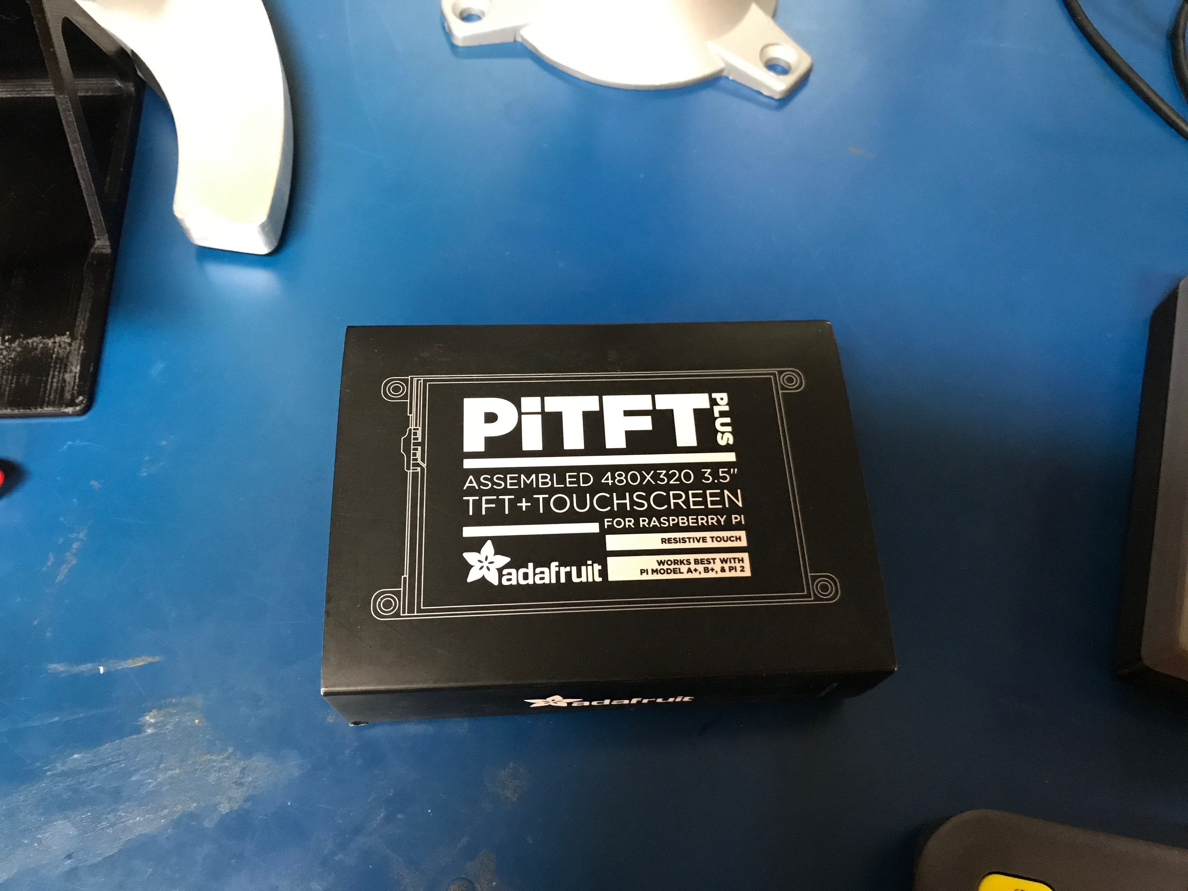\n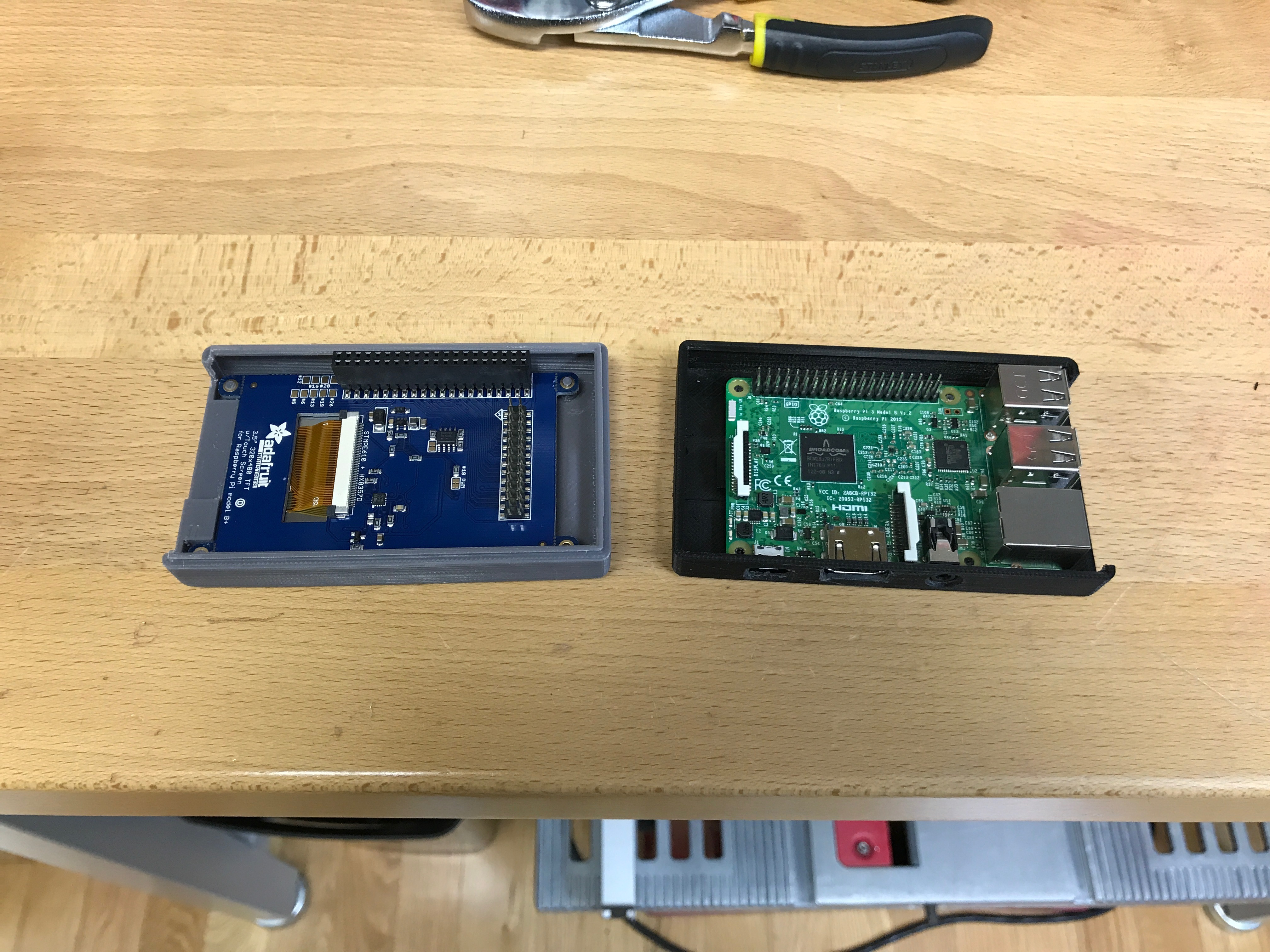\n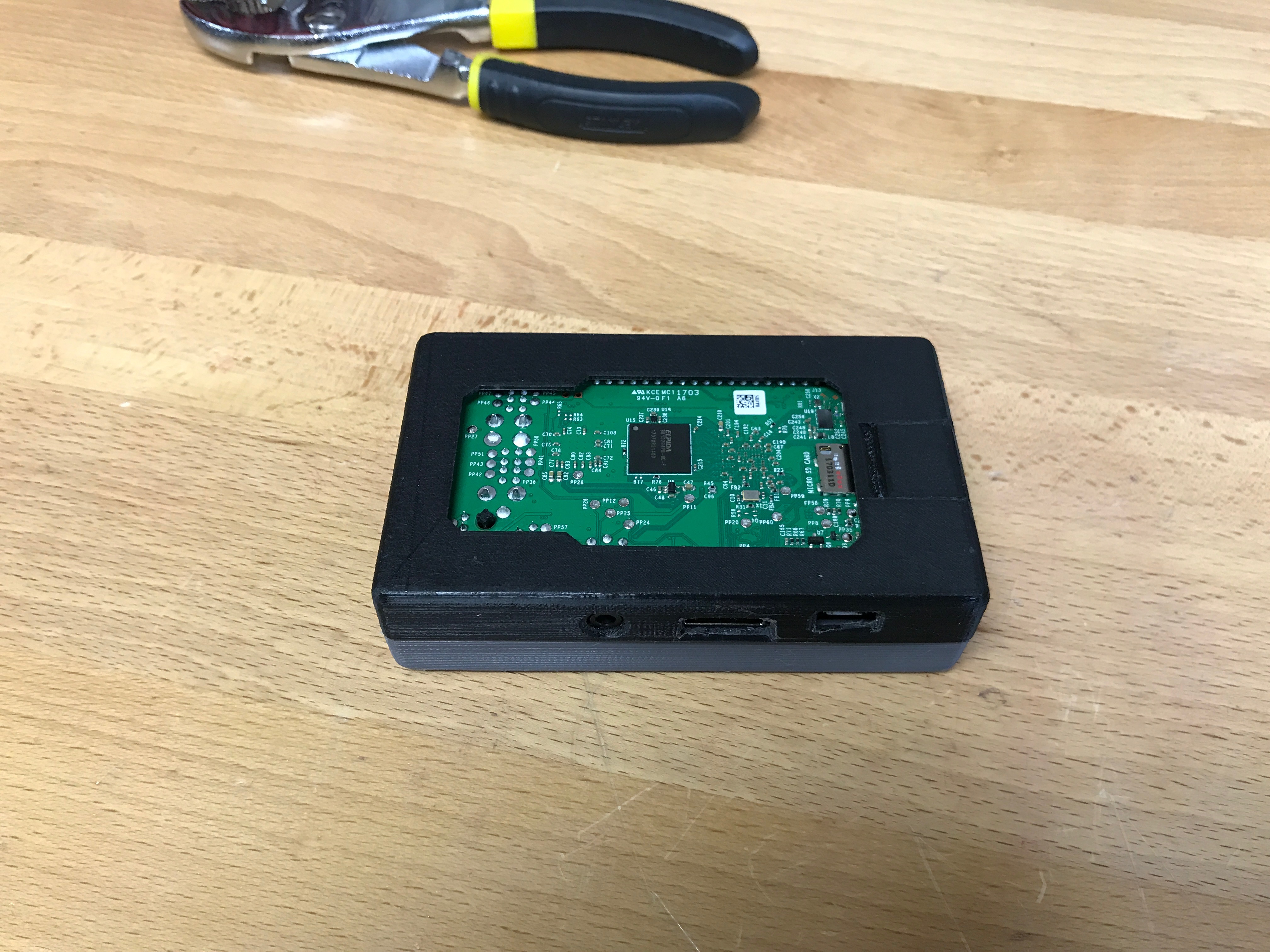\n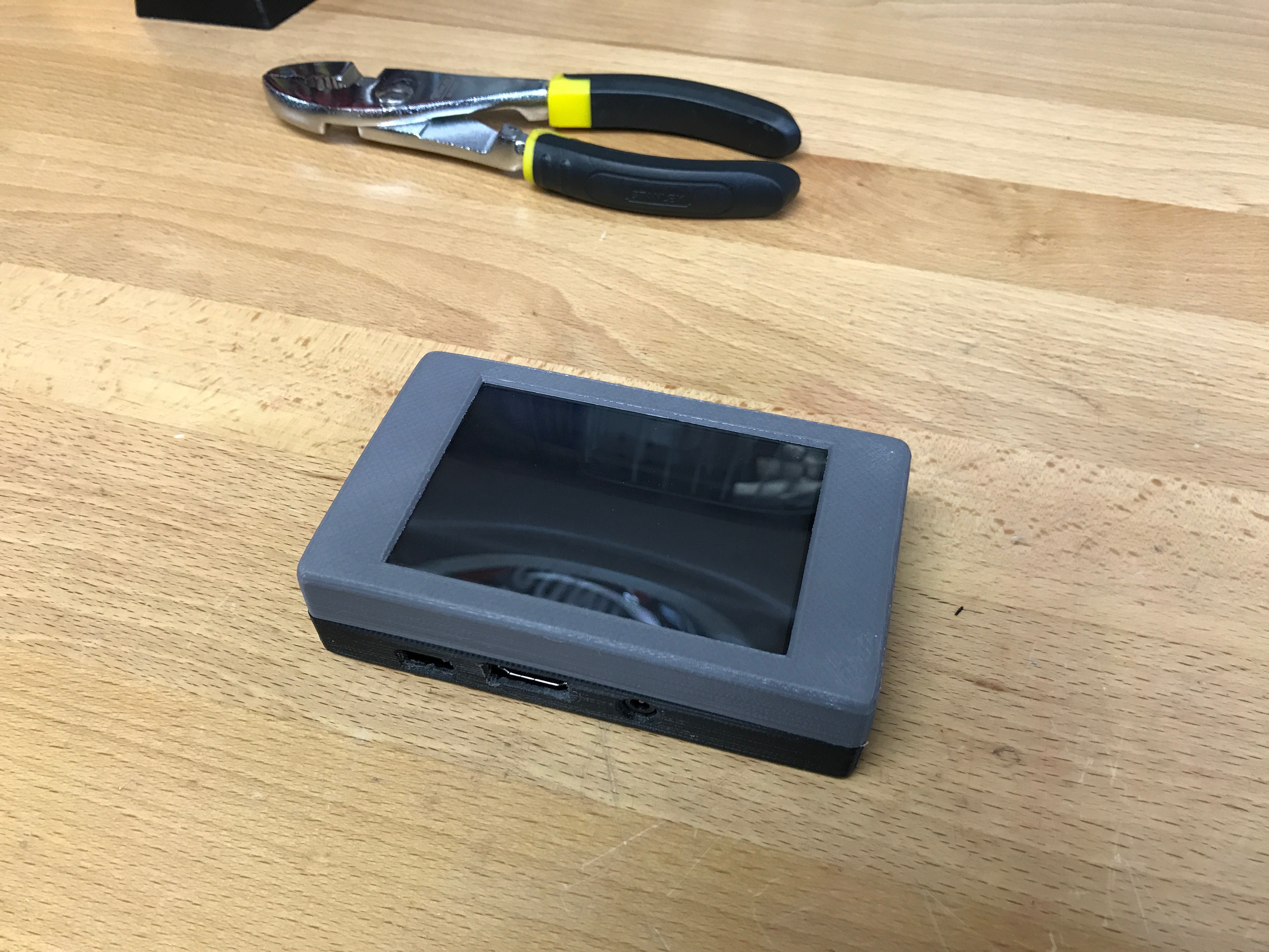\n\n\n### Getting Started\n\nThis is a very simple project. Here are the things you will need:\n\n* Raspberry Pi 3\n* PiTFT Plus 3.5\"\n* SD Card\n* 3D Printer\n\nMost of this is already covered in Adafruit's fantastic guide: https://learn.adafruit.com/3-dot-5-pitft-octoprint-rig/overview.\n\nMy approach has been updated and is a bit more bare bones... You will download the latest **Raspbian Jessie Lite** from https://www.raspberrypi.org/downloads/raspbian/, and burn it to your SD card. \n\nDo the usual Raspberry Pi setup process... Change the default password, enable SSH, get on to your wifi, etc. Once raspbian is running and secured on your Pi3 you can proceed with this guide.\n\n---\n\n### Install required packages\n\nAs root (`sudo -i`), please do the following:\n```\napt-get install python-pip python-dev python-setuptools python-virtualenv git libyaml-dev build-essential chromium-browser raspi-gpio xcompmgr dbus-x11 libgl1-mesa-dri xserver-xorg xserver-xorg-video-fbdev xserver-xorg-input-evdev xinit xfonts-100dpi xfonts-75dpi xfonts-cyrillic xfonts-scalable xinput ttf-mscorefonts-installer xinput-calibrator\n```\n---\n\n### Base setup\n\nCreate the octoprint user. This user will be used to run both the backend and the frontend of octoprint:\n\n```\nadduser --disabled-password --disabled-login --gecos \"\" octoprint \n\nusermod -a -G cdrom,audio,video,render,plugdev,users,dialout,dip,input,tty octoprint \n```\n\nFix the xorg config permissions so that a non-root user can run X correctly:\n\n```\nchmod ug+s /usr/lib/xorg/Xorg\n```\n\nNow we will update a few X config files to optimize for this use case:\n\n**edit: `/etc/X11/Xwrapper.config`**\n```\nallowed_users=anybody\nneeds_root_rights=no\n```\n\n**edit: `/etc/kbd/config`**\n```\nBLANK_TIME=0 \nBLANK_DPMS=off \nPOWERDOWN_TIME=0 \n```\n\n**edit: `/etc/X11/xinit/xinitrc`**\n```\nxset s noblank \nxset s off \nxset -dpms \n```\n\n---\n\n### Install Octoprint\n\nSwitch from root to the octoprint user `su octoprint`:\n\n```\ncd /home/octoprint\n\ngit clone https://github.com/foosel/OctoPrint.git\n\ncd OctoPrint\n\nvirtualenv venv\n./venv/bin/pip install pip --upgrade\n./venv/bin/pip install setuptools==7.0\n./venv/bin/python setup.py install\n\nmkdir ~/.octoprint\n```\n\nThis should leave you with a happy install of octoprint located at `/home/octoprint/Octoprint`.\n\n### Setup systemd services\n\n**edit: `/etc/systemd/system/octoprint-backend.service`**\n```\n[Unit]\n Description=OctoPrint service\n\n[Service]\n User=octoprint\n ExecStart=/home/octoprint/OctoPrint/venv/bin/octoprint\n\n[Install]\n WantedBy=multi-user.target\n```\n\n\n**edit: `/etc/systemd/system/octoprint-frontend.service`**\n```\n[Unit]\nDescription = Octoprint Frontend \nAfter = systemd-user-sessions.service network.target sound.target\n\n[Service]\nUser = octoprint \nGroup = octoprint \nType = simple \nExecStart = /usr/bin/xinit /usr/bin/dbus-launch --exit-with-session /usr/bin/chromium-browser --start-maximized --window-size=480,320 --window-position=0,0 --disable-restore-background-contents --noerordialogs --disable-session-crashed-bubble --disable-infobars --disable-pinch --overscroll-history-navigation=0 --incognito --kiosk http://127.0.0.1:5000 -- :0 -s 0 dpms -nocursor -nolisten tcp vt7 \nRestart = on-abort \nRestartSec = 5\n\n[Install]\nWantedBy = multi-user.target\n```\n\nEnable both services to start at boot:\n```\nsystemctl enable octoprint-backend.service\nsystemctl enable octoprint-frontend.service\n```\n\n---\n\n### Octoprint setup\n\nLog in to your octoprint instance using a browser on your computer. It should be something like http://**YOUR___PI___IP**:5000. You can find your Pi's ip address by running `ifconfig` as root. You will be presented with the \"Setup Wizard\". Follow the instructions to complete the setup process. \n \n*To keep things simple I recommend **DISABLING** access control. I would not recommend this if you are putting your Raspberry Pi on a public network.*\n\n--- \n### TouchUI plugin\n\nTo best fit on the 480x320 screen, you should enable the TouchUI plugin. On your computer connect to the octoprint instance running on the Raspberry Pi (*instructions above*). \"Under the settings section, goto the plugin manager and search for \"Touch UI\", then click the install button.\" --[Adafruit](https://learn.adafruit.com/3-dot-5-pitft-octoprint-rig/software)\n\n---\n\n### Enable the PiTFT\n\nAdafruit has a guide: https://learn.adafruit.com/adafruit-pitft-3-dot-5-touch-screen-for-raspberry-pi/easy-install, but it doesnt seem to play nice with the latest Raspbian.\n\nRun the following as root (`sudo -i`):\n```\necho \"deb http://apt.adafruit.com/raspbian/ jessie main\" \u003e\u003e /etc/apt/sources.list\n\nwget -O - -q https://apt.adafruit.com/apt.adafruit.com.gpg.key | apt-key add -\n\napt-get update\napt-get install -y adafruit-pitft-helper\n```\n\nThen run adafruit-pitft-helper:\n```\nadafruit-pitft-helper -t 35r\n```\n\nCheck `/boot/config.txt` to ensure the defined orientation will work for you. The line to review should look like:\n```\ndtoverlay=pitft35r,rotate=90,speed=42000000,fps=20\n```\n\nThe rotate= variable tells the driver to rotate the screen 0, 90, 180, or 270 degrees. \n\n * **0** is portrait, with the bottom near the USB jacks.\n * **90** is landscape, with the bottom of the screen near the headphone jack.\n * **180** is portrait, with the top near the USB jacks.\n * **270** is landscape, with the top of the screen near the headphone jack.\n\nNow reboot (`reboot`).\n\nAfter the reboot (in theory) you will see the octoprint web interface on your PiTFT. But you will need to calibrate the touchscreen before you can interact with it.\n\n---\n\n### Touch calibration\n\nAs root (`sudo -i`) run the following:\n```\nDISPLAY=:0.0 xinput_calibrator\n```\n\nFollow the onscreen calibration process:\n\u003cp align=\"center\"\u003e\n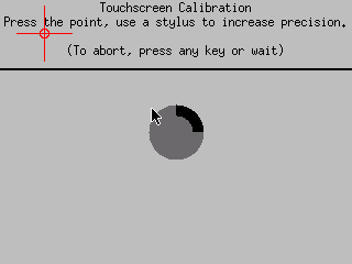\n\u003c/p\u003e\n\nOnce complete you should have a snippet of config to paste relevant to your touch screen.\n\n\n**edit: `/etc/X11/xorg.conf.d/99-calibration.conf`** and paste the output you got from xinput_calibrator.\n\n**Example output:** \n```\nSection \"InputClass\"\n\tIdentifier\t\"calibration\"\n\tMatchProduct\t\"stmpe-ts\"\n\tOption\t\"Calibration\"\t\"3932 82 141 3877\"\n\tOption\t\"SwapAxes\"\t\"1\"\n\tOption \"InvertX\" \"1\"\n\tOption \"InvertY\" \"1\"\nEndSection\n```\n\nIf your config does not contain **InvertX** or **InvertY** (*mine didn't*), you can add it manually to fix input inversion problems you may have.\n\nReboot (`reboot`), and enjoy your octoprint rig!.\n\n---\n\n### My Octoprint controller\n\nI mounted my octoprint controller to the shelving that I have my 3D printers on using double sided adhesive. Overall I am very impressed with how simple octoprint is and how well it works with my Anet A8 3D printer. \n\n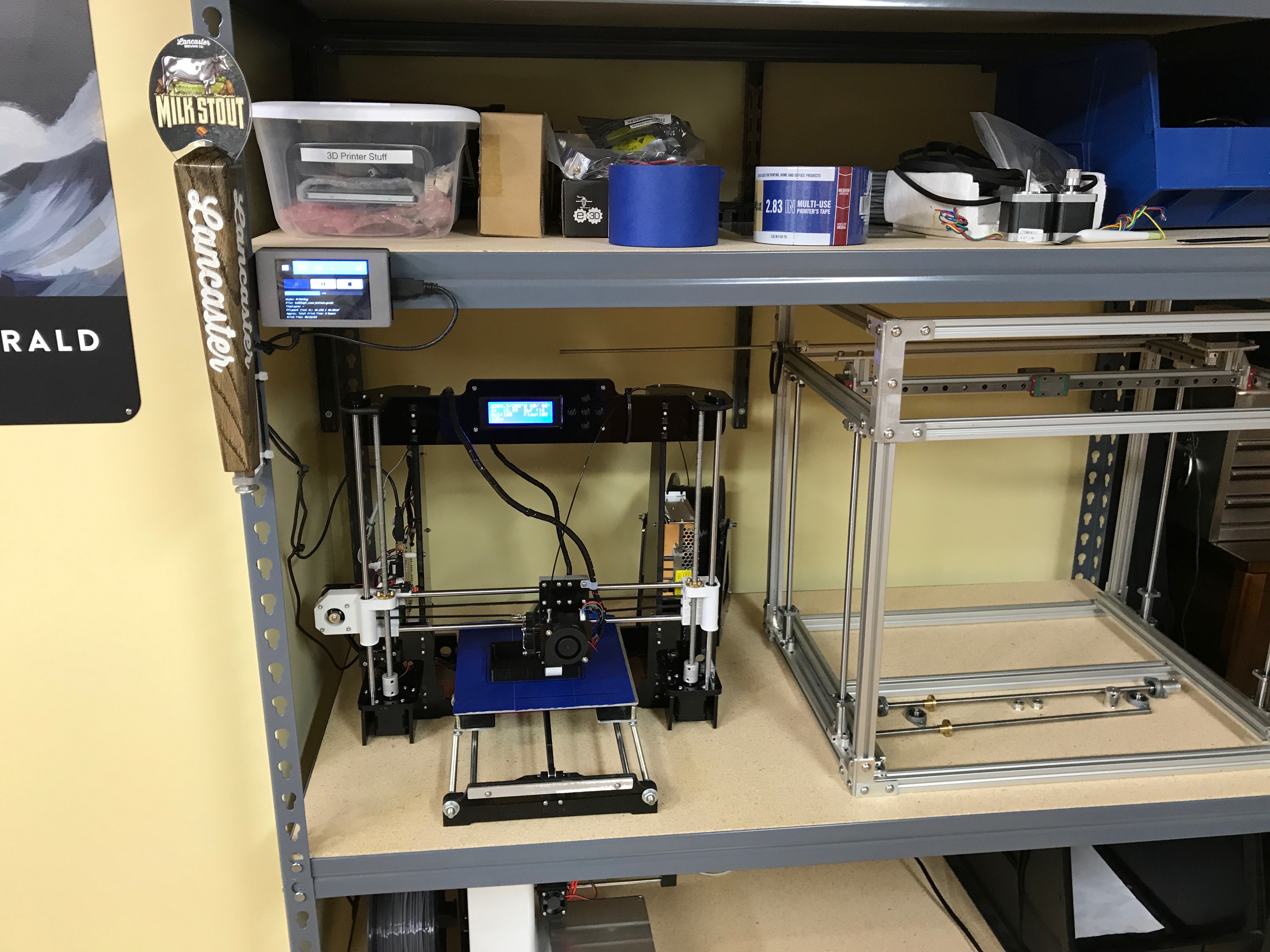\n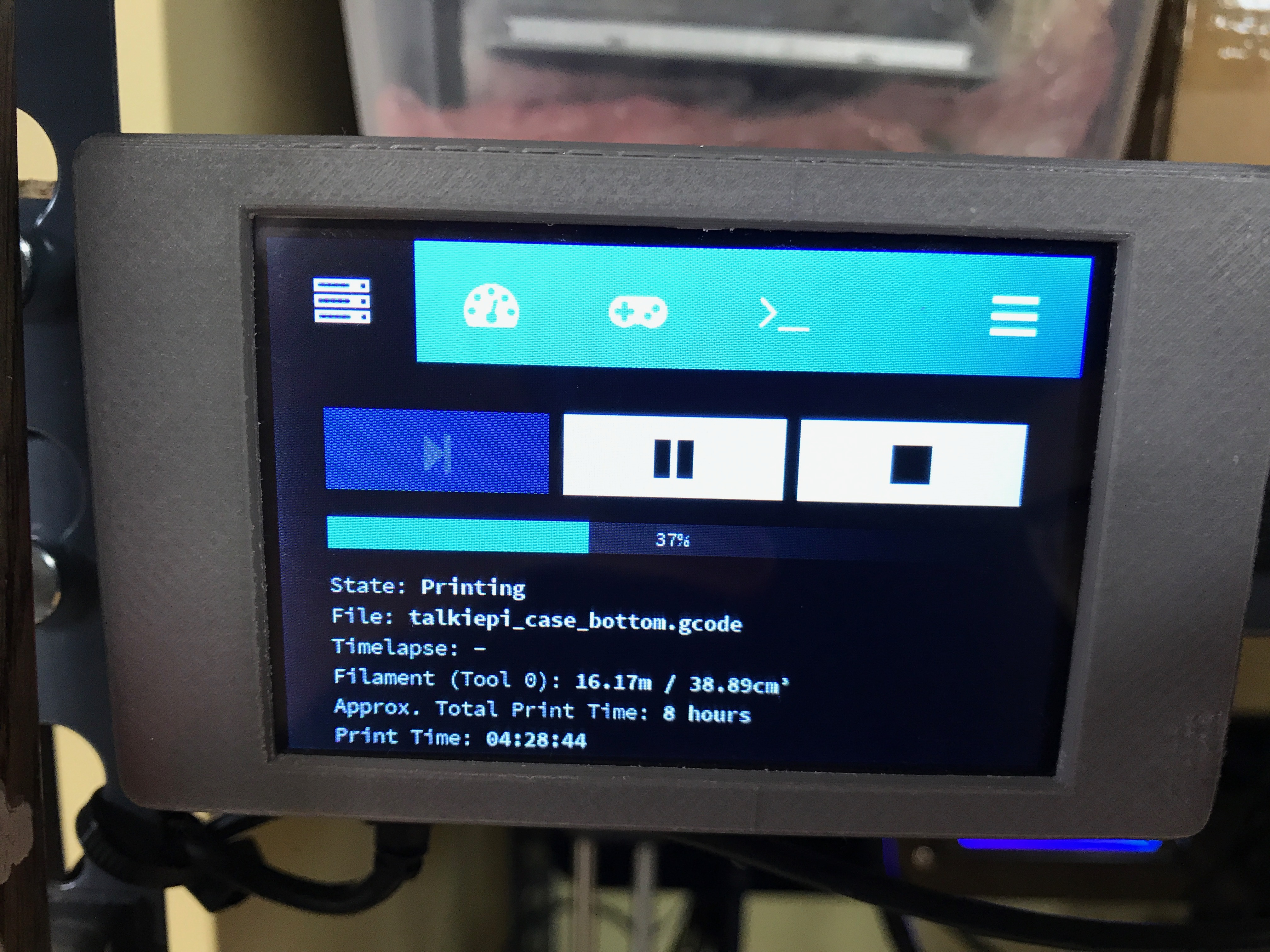\n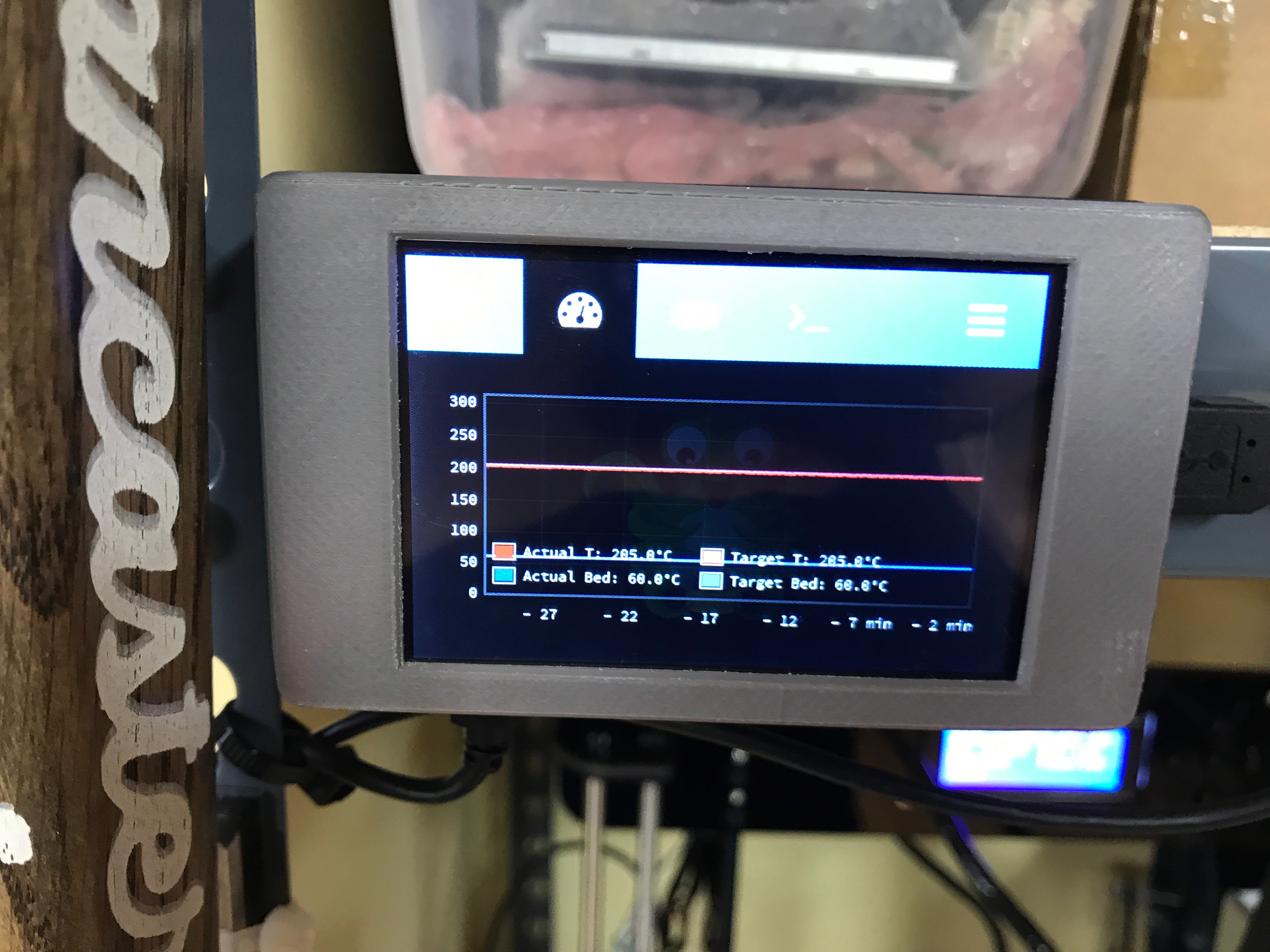\n","html":"\u003cp\u003eAs everyone knows I love my Raspberry Pis. I\u0026#39;ll put them in whatever I can fit them in. I am in the process of finishing my 3D printer rack and I wanted to get my new Anet A8 printer on wifi so that I didn\u0026#39;t need to shuffle the difficult to remove SD card from it when I wanted to print something.\u003c/p\u003e\n\u003cimg src=\"/content/images/2017/07/IMG_1559.jpg\" alt=\"\"\u003e\n\u003cp\u003eAlong comes \u003ca href=\"http://octoprint.org\" rel=\"nofollow\"\u003eOctoprint\u003c/a\u003e... Now, there are plenty of \u0026#34;how to install octoprint on a Raspberry Pi\u0026#34; documents out there, but nothing quite as pedantic as I would have liked. So I set off to do it my way.\u003c/p\u003e\n\u003cp\u003eThis project uses a fantastic Adafruit designed 3D printed case: \u003ca href=\"https://learn.adafruit.com/3-dot-5-pitft-octoprint-rig/3d-printed-case\" rel=\"nofollow\"\u003ehttps://learn.adafruit.com/3-dot-5-pitft-octoprint-rig/3d-printed-case\u003c/a\u003e to wrap a \u003ca href=\"https://www.adafruit.com/product/3055\" rel=\"nofollow\"\u003eRaspberry Pi 3\u003c/a\u003e + \u003ca href=\"https://www.adafruit.com/product/2441\" rel=\"nofollow\"\u003eAdafruit PiTFT Plus 3.5\u0026#34; touch screen\u003c/a\u003e.\u003c/p\u003e\n\u003cimg src=\"/content/images/2017/07/IMG_1532.jpg\" alt=\"\"\u003e\n\u003cimg src=\"/content/images/2017/07/IMG_1529.jpg\" alt=\"\"\u003e\n\u003cimg src=\"/content/images/2017/07/IMG_1531.jpg\" alt=\"\"\u003e\n\u003cimg src=\"/content/images/2017/07/IMG_1530.jpg\" alt=\"\"\u003e\n\u003ch3\u003eGetting Started\u003c/h3\u003e\n\u003cp\u003eThis is a very simple project. Here are the things you will need:\u003c/p\u003e\n\u003cul\u003e\n\u003cli\u003eRaspberry Pi 3\u003c/li\u003e\n\u003cli\u003ePiTFT Plus 3.5\u0026#34;\u003c/li\u003e\n\u003cli\u003eSD Card\u003c/li\u003e\n\u003cli\u003e3D Printer\u003c/li\u003e\n\u003c/ul\u003e\n\u003cp\u003eMost of this is already covered in Adafruit\u0026#39;s fantastic guide: \u003ca href=\"https://learn.adafruit.com/3-dot-5-pitft-octoprint-rig/overview\" rel=\"nofollow\"\u003ehttps://learn.adafruit.com/3-dot-5-pitft-octoprint-rig/overview\u003c/a\u003e.\u003c/p\u003e\n\u003cp\u003eMy approach has been updated and is a bit more bare bones... You will download the latest \u003cstrong\u003eRaspbian Jessie Lite\u003c/strong\u003e from \u003ca href=\"https://www.raspberrypi.org/downloads/raspbian/\" rel=\"nofollow\"\u003ehttps://www.raspberrypi.org/downloads/raspbian/\u003c/a\u003e, and burn it to your SD card.\u003c/p\u003e\n\u003cp\u003eDo the usual Raspberry Pi setup process... Change the default password, enable SSH, get on to your wifi, etc. Once raspbian is running and secured on your Pi3 you can proceed with this guide.\u003c/p\u003e\n\u003chr\u003e\n\u003ch3\u003eInstall required packages\u003c/h3\u003e\n\u003cp\u003eAs root (\u003ccode\u003esudo -i\u003c/code\u003e), please do the following:\u003c/p\u003e\n\u003cpre\u003e\u003ccode\u003eapt-get install python-pip python-dev python-setuptools python-virtualenv git libyaml-dev build-essential chromium-browser raspi-gpio xcompmgr dbus-x11 libgl1-mesa-dri xserver-xorg xserver-xorg-video-fbdev xserver-xorg-input-evdev xinit xfonts-100dpi xfonts-75dpi xfonts-cyrillic xfonts-scalable xinput ttf-mscorefonts-installer xinput-calibrator\n\u003c/code\u003e\u003c/pre\u003e\n\u003chr\u003e\n\u003ch3\u003eBase setup\u003c/h3\u003e\n\u003cp\u003eCreate the octoprint user. This user will be used to run both the backend and the frontend of octoprint:\u003c/p\u003e\n\u003cpre\u003e\u003ccode\u003eadduser --disabled-password --disabled-login --gecos \u0026#34;\u0026#34; octoprint \n\nusermod -a -G cdrom,audio,video,render,plugdev,users,dialout,dip,input,tty octoprint \n\u003c/code\u003e\u003c/pre\u003e\n\u003cp\u003eFix the xorg config permissions so that a non-root user can run X correctly:\u003c/p\u003e\n\u003cpre\u003e\u003ccode\u003echmod ug+s /usr/lib/xorg/Xorg\n\u003c/code\u003e\u003c/pre\u003e\n\u003cp\u003eNow we will update a few X config files to optimize for this use case:\u003c/p\u003e\n\u003cp\u003e\u003cstrong\u003eedit: \u003ccode\u003e/etc/X11/Xwrapper.config\u003c/code\u003e\u003c/strong\u003e\u003c/p\u003e\n\u003cpre\u003e\u003ccode\u003eallowed_users=anybody\nneeds_root_rights=no\n\u003c/code\u003e\u003c/pre\u003e\n\u003cp\u003e\u003cstrong\u003eedit: \u003ccode\u003e/etc/kbd/config\u003c/code\u003e\u003c/strong\u003e\u003c/p\u003e\n\u003cpre\u003e\u003ccode\u003eBLANK_TIME=0 \nBLANK_DPMS=off \nPOWERDOWN_TIME=0 \n\u003c/code\u003e\u003c/pre\u003e\n\u003cp\u003e\u003cstrong\u003eedit: \u003ccode\u003e/etc/X11/xinit/xinitrc\u003c/code\u003e\u003c/strong\u003e\u003c/p\u003e\n\u003cpre\u003e\u003ccode\u003exset s noblank \nxset s off \nxset -dpms \n\u003c/code\u003e\u003c/pre\u003e\n\u003chr\u003e\n\u003ch3\u003eInstall Octoprint\u003c/h3\u003e\n\u003cp\u003eSwitch from root to the octoprint user \u003ccode\u003esu octoprint\u003c/code\u003e:\u003c/p\u003e\n\u003cpre\u003e\u003ccode\u003ecd /home/octoprint\n\ngit clone https://github.com/foosel/OctoPrint.git\n\ncd OctoPrint\n\nvirtualenv venv\n./venv/bin/pip install pip --upgrade\n./venv/bin/pip install setuptools==7.0\n./venv/bin/python setup.py install\n\nmkdir ~/.octoprint\n\u003c/code\u003e\u003c/pre\u003e\n\u003cp\u003eThis should leave you with a happy install of octoprint located at \u003ccode\u003e/home/octoprint/Octoprint\u003c/code\u003e.\u003c/p\u003e\n\u003ch3\u003eSetup systemd services\u003c/h3\u003e\n\u003cp\u003e\u003cstrong\u003eedit: \u003ccode\u003e/etc/systemd/system/octoprint-backend.service\u003c/code\u003e\u003c/strong\u003e\u003c/p\u003e\n\u003cpre\u003e\u003ccode\u003e[Unit]\n Description=OctoPrint service\n\n[Service]\n User=octoprint\n ExecStart=/home/octoprint/OctoPrint/venv/bin/octoprint\n\n[Install]\n WantedBy=multi-user.target\n\u003c/code\u003e\u003c/pre\u003e\n\u003cp\u003e\u003cstrong\u003eedit: \u003ccode\u003e/etc/systemd/system/octoprint-frontend.service\u003c/code\u003e\u003c/strong\u003e\u003c/p\u003e\n\u003cpre\u003e\u003ccode\u003e[Unit]\nDescription = Octoprint Frontend \nAfter = systemd-user-sessions.service network.target sound.target\n\n[Service]\nUser = octoprint \nGroup = octoprint \nType = simple \nExecStart = /usr/bin/xinit /usr/bin/dbus-launch --exit-with-session /usr/bin/chromium-browser --start-maximized --window-size=480,320 --window-position=0,0 --disable-restore-background-contents --noerordialogs --disable-session-crashed-bubble --disable-infobars --disable-pinch --overscroll-history-navigation=0 --incognito --kiosk http://127.0.0.1:5000 -- :0 -s 0 dpms -nocursor -nolisten tcp vt7 \nRestart = on-abort \nRestartSec = 5\n\n[Install]\nWantedBy = multi-user.target\n\u003c/code\u003e\u003c/pre\u003e\n\u003cp\u003eEnable both services to start at boot:\u003c/p\u003e\n\u003cpre\u003e\u003ccode\u003esystemctl enable octoprint-backend.service\nsystemctl enable octoprint-frontend.service\n\u003c/code\u003e\u003c/pre\u003e\n\u003chr\u003e\n\u003ch3\u003eOctoprint setup\u003c/h3\u003e\n\u003cp\u003eLog in to your octoprint instance using a browser on your computer. It should be something like http://\u003cstrong\u003eYOUR___PI___IP\u003c/strong\u003e:5000. You can find your Pi\u0026#39;s ip address by running \u003ccode\u003eifconfig\u003c/code\u003e as root. You will be presented with the \u0026#34;Setup Wizard\u0026#34;. Follow the instructions to complete the setup process.\u003c/p\u003e\n\u003cp\u003e\u003cem\u003eTo keep things simple I recommend \u003cstrong\u003eDISABLING\u003c/strong\u003e access control. I would not recommend this if you are putting your Raspberry Pi on a public network.\u003c/em\u003e\u003c/p\u003e\n\u003chr\u003e\n\u003ch3\u003eTouchUI plugin\u003c/h3\u003e\n\u003cp\u003eTo best fit on the 480x320 screen, you should enable the TouchUI plugin. On your computer connect to the octoprint instance running on the Raspberry Pi (\u003cem\u003einstructions above\u003c/em\u003e). \u0026#34;Under the settings section, goto the plugin manager and search for \u0026#34;Touch UI\u0026#34;, then click the install button.\u0026#34; --\u003ca href=\"https://learn.adafruit.com/3-dot-5-pitft-octoprint-rig/software\" rel=\"nofollow\"\u003eAdafruit\u003c/a\u003e\u003c/p\u003e\n\u003chr\u003e\n\u003ch3\u003eEnable the PiTFT\u003c/h3\u003e\n\u003cp\u003eAdafruit has a guide: \u003ca href=\"https://learn.adafruit.com/adafruit-pitft-3-dot-5-touch-screen-for-raspberry-pi/easy-install\" rel=\"nofollow\"\u003ehttps://learn.adafruit.com/adafruit-pitft-3-dot-5-touch-screen-for-raspberry-pi/easy-install\u003c/a\u003e, but it doesnt seem to play nice with the latest Raspbian.\u003c/p\u003e\n\u003cp\u003eRun the following as root (\u003ccode\u003esudo -i\u003c/code\u003e):\u003c/p\u003e\n\u003cpre\u003e\u003ccode\u003eecho \u0026#34;deb http://apt.adafruit.com/raspbian/ jessie main\u0026#34; \u0026gt;\u0026gt; /etc/apt/sources.list\n\nwget -O - -q https://apt.adafruit.com/apt.adafruit.com.gpg.key | apt-key add -\n\napt-get update\napt-get install -y adafruit-pitft-helper\n\u003c/code\u003e\u003c/pre\u003e\n\u003cp\u003eThen run adafruit-pitft-helper:\u003c/p\u003e\n\u003cpre\u003e\u003ccode\u003eadafruit-pitft-helper -t 35r\n\u003c/code\u003e\u003c/pre\u003e\n\u003cp\u003eCheck \u003ccode\u003e/boot/config.txt\u003c/code\u003e to ensure the defined orientation will work for you. The line to review should look like:\u003c/p\u003e\n\u003cpre\u003e\u003ccode\u003edtoverlay=pitft35r,rotate=90,speed=42000000,fps=20\n\u003c/code\u003e\u003c/pre\u003e\n\u003cp\u003eThe rotate= variable tells the driver to rotate the screen 0, 90, 180, or 270 degrees.\u003c/p\u003e\n\u003cul\u003e\n\u003cli\u003e\u003cstrong\u003e0\u003c/strong\u003e is portrait, with the bottom near the USB jacks.\u003c/li\u003e\n\u003cli\u003e\u003cstrong\u003e90\u003c/strong\u003e is landscape, with the bottom of the screen near the headphone jack.\u003c/li\u003e\n\u003cli\u003e\u003cstrong\u003e180\u003c/strong\u003e is portrait, with the top near the USB jacks.\u003c/li\u003e\n\u003cli\u003e\u003cstrong\u003e270\u003c/strong\u003e is landscape, with the top of the screen near the headphone jack.\u003c/li\u003e\n\u003c/ul\u003e\n\u003cp\u003eNow reboot (\u003ccode\u003ereboot\u003c/code\u003e).\u003c/p\u003e\n\u003cp\u003eAfter the reboot (in theory) you will see the octoprint web interface on your PiTFT. But you will need to calibrate the touchscreen before you can interact with it.\u003c/p\u003e\n\u003chr\u003e\n\u003ch3\u003eTouch calibration\u003c/h3\u003e\n\u003cp\u003eAs root (\u003ccode\u003esudo -i\u003c/code\u003e) run the following:\u003c/p\u003e\n\u003cpre\u003e\u003ccode\u003eDISPLAY=:0.0 xinput_calibrator\n\u003c/code\u003e\u003c/pre\u003e\n\u003cp\u003eFollow the onscreen calibration process:\u003c/p\u003e\n\u003cp align=\"center\"\u003e\n\u003cimg src=\"/content/images/2017/07/raspberry_pi_xinput.png\" alt=\"\"\u003e\n\u003c/p\u003e\n\u003cp\u003eOnce complete you should have a snippet of config to paste relevant to your touch screen.\u003c/p\u003e\n\u003cp\u003e\u003cstrong\u003eedit: \u003ccode\u003e/etc/X11/xorg.conf.d/99-calibration.conf\u003c/code\u003e\u003c/strong\u003e and paste the output you got from xinput_calibrator.\u003c/p\u003e\n\u003cp\u003e\u003cstrong\u003eExample output:\u003c/strong\u003e\u003c/p\u003e\n\u003cpre\u003e\u003ccode\u003eSection \u0026#34;InputClass\u0026#34;\n\tIdentifier\t\u0026#34;calibration\u0026#34;\n\tMatchProduct\t\u0026#34;stmpe-ts\u0026#34;\n\tOption\t\u0026#34;Calibration\u0026#34;\t\u0026#34;3932 82 141 3877\u0026#34;\n\tOption\t\u0026#34;SwapAxes\u0026#34;\t\u0026#34;1\u0026#34;\n\tOption \u0026#34;InvertX\u0026#34; \u0026#34;1\u0026#34;\n\tOption \u0026#34;InvertY\u0026#34; \u0026#34;1\u0026#34;\nEndSection\n\u003c/code\u003e\u003c/pre\u003e\n\u003cp\u003eIf your config does not contain \u003cstrong\u003eInvertX\u003c/strong\u003e or \u003cstrong\u003eInvertY\u003c/strong\u003e (\u003cem\u003emine didn\u0026#39;t\u003c/em\u003e), you can add it manually to fix input inversion problems you may have.\u003c/p\u003e\n\u003cp\u003eReboot (\u003ccode\u003ereboot\u003c/code\u003e), and enjoy your octoprint rig!.\u003c/p\u003e\n\u003chr\u003e\n\u003ch3\u003eMy Octoprint controller\u003c/h3\u003e\n\u003cp\u003eI mounted my octoprint controller to the shelving that I have my 3D printers on using double sided adhesive. Overall I am very impressed with how simple octoprint is and how well it works with my Anet A8 3D printer.\u003c/p\u003e\n\u003cimg src=\"/content/images/2017/07/IMG_1557.jpg\" alt=\"\"\u003e\n\u003cimg src=\"/content/images/2017/07/IMG_1555.jpg\" alt=\"\"\u003e\n\u003cimg src=\"/content/images/2017/07/IMG_1556.jpg\" alt=\"\"\u003e\n","excerpt":"","metaTitle":"","metaDescription":"","status":"published","featured":false,"publishedAt":"2017-07-21T02:18:30Z","authorId":"190160de54f2192bd5b8734ec8808086","authorName":"Daniel Chote","authorSlug":"daniel","heroMediaId":"51fc6de0bddbd56cfebbf24db5659465","projectId":"","tags":[{"id":"b529314e428273696b02c474dcf56132","name":"Raspberry Pi","slug":"raspberry-pi"},{"id":"f9ecad390ed765b2bb4ae55d9faa7311","name":"Octoprint","slug":"octoprint"},{"id":"e58b4788e99c9f53befd1e47b8073250","name":"3D Printing","slug":"3d-printing"}],"createdAt":"2026-10-18T13:16:27Z","updatedAt":"2026-10-18T13:16:27Z"},{"id":"3b428344cc73fc1bff50ed42b01a17ca","siteId":"projectable","slug":"optimize-my-pi-wi-fi","title":"Optimize my pi wi fi","markdown":"## Raspberry Pi wifi on enterprise wifi hardware\n\nI've been poking around to get stable wifi with my raspberry pi devices on my Aruba Networks wireless network. My network is far from a typical house solution. I have a rack, a server, Juniper router, Juniper switch, and an Aruba Networks wifi controller, with an access point on each floor of our house. \n\nHaving multiple access points all broadcast the same SSID seems to have uncovered an issue with the Raspberry Pi 3's Broadcom brcmfmac firmware/kernel module. \n\nThe issue I was experiencing was that the wifi would constantly connect/disconnect, then eventually loose connectivity entirely. I ended up using a 8192cu based USB adapter to overcome the issue. However, with a little poking around, I think I have solved the issue, thanks to a suggestion from [@ukscone](https://twitter.com/ukscone/status/774412941873512449).\u0010 \n\nI looked at the module options for the brcmfmac kernel module:\n\n`systool -a -v -m brcmfmac `\n\n```\nModule = \"brcmfmac\"\n\n Attributes:\n coresize = \"186343\"\n initsize = \"0\"\n initstate = \"live\"\n refcnt = \"0\"\n srcversion = \"B33E7691EAF20C9A34D6807\"\n taint = \"\"\n uevent = \u003cstore method only\u003e\n\n Parameters:\n alternative_fw_path = \n debug = \"0\"\n fcmode = \"0\"\n roamoff = \"1\"\n\n Sections:\n .ARM.exidx.exit.text= \"0x7f2ee574\"\n .ARM.exidx.init.text= \"0x7f2ee550\"\n .ARM.exidx = \"0x7f2ef6d4\"\n .ARM.extab.exit.text= \"0x7f2ee568\"\n .ARM.extab = \"0x7f2ee57c\"\n .ARM.extab.init.text= \"0x7f2ee52c\"\n .alt.smp.init = \"0x7f2ee504\"\n .bss = \"0x7f2f1140\"\n .data = \"0x7f2f0264\"\n .data.unlikely = \"0x7f2f0f28\"\n .exit.text = \"0x7f2e6de0\"\n .gnu.linkonce.this_module= \"0x7f2f0f40\"\n .init.text = \"0x7f306000\"\n .note.gnu.build-id = \"0x7f2e6e04\"\n .rodata.str = \"0x7f2e86e0\"\n .rodata = \"0x7f2e6e28\"\n .rodata.str1.4 = \"0x7f2e8c9c\"\n .strtab = \"0x7f30e17c\"\n .symtab = \"0x7f30609c\"\n .text = \"0x7f2c9000\"\n __bug_table = \"0x7f2e8ab0\"\n __mcount_loc = \"0x7f2edf3c\"\n __param = \"0x7f2edeb0\"\n\n```\n\nNot a lot to run on compared to the HUGE amount that the 8192cu module has, but there was the one for roamoff, so I tried setting that and surprisingly it seems to have resolved the issues on my wifi network!\n\n---\n\n### Turn off firmware roaming support\n\nCreate `/etc/modprobe.d/brcmfmac.conf` and add the following:\n```\noptions brcmfmac roamoff=1\n```\n\nFor the sake of compliance, I also edited `/etc/default/crda` and set `REGDOMAIN` to **US** (my wifi equipment is set for **US**; you would set this to your country code)\n\n```\nREGDOMAIN=US\n```\n\n\nIn addition to applying the module config, I suggest disabling power save and bluetooth if you don't need it.\n\n---\n\n### Disable wifi power saving mode\n\nEdit `/etc/network/interfaces` and add `up iw wlan0 set power_save off` to your wlan0 definition:\n\n```\nallow-hotplug wlan0\niface wlan0 inet manual\n wpa-conf /etc/wpa_supplicant/wpa_supplicant.conf\n up iw wlan0 set power_save off\n```\n\n---\n\n### Disable Raspberry Pi 3's bluetooth\n\nEdit `/boot/config.txt` and append `dtoverlay=pi3-disable-bt` to the end of the file. \n\nThen as root (`sudo -i`) disable the bluetooth services:\n\n```\nsystemctl disable bluetooth.service\nsystemctl disable hciuart.service\n```\n\n\n---\n\n### My 8192cu USB config\n\nI'm including this here as a resource also. I found that the 8192cu connectivity to my Aruba Networks wifi was also very spotty until I did the following.\n\nCreate `/etc/modprobe.d/8192cu.conf` and add the following:\n\n```\noptions 8192cu rtw_power_mgnt=0 rtw_enusbss=0\n```\n\n---\n\n### My r8188eu (HubPiWi) config\n\nSame as the 8192cu, to ensure reliable a consistent wifi connection, we do the following.\n\nCreate `/etc/modprobe.d/r8188eu.conf` and add the following:\n\n```\noptions r8188eu rtw_power_mgnt=0 rtw_enusbss=0\n```","html":"\u003ch2\u003eRaspberry Pi wifi on enterprise wifi hardware\u003c/h2\u003e\n\u003cp\u003eI\u0026#39;ve been poking around to get stable wifi with my raspberry pi devices on my Aruba Networks wireless network. My network is far from a typical house solution. I have a rack, a server, Juniper router, Juniper switch, and an Aruba Networks wifi controller, with an access point on each floor of our house.\u003c/p\u003e\n\u003cp\u003eHaving multiple access points all broadcast the same SSID seems to have uncovered an issue with the Raspberry Pi 3\u0026#39;s Broadcom brcmfmac firmware/kernel module.\u003c/p\u003e\n\u003cp\u003eThe issue I was experiencing was that the wifi would constantly connect/disconnect, then eventually loose connectivity entirely. I ended up using a 8192cu based USB adapter to overcome the issue. However, with a little poking around, I think I have solved the issue, thanks to a suggestion from \u003ca href=\"https://twitter.com/ukscone/status/774412941873512449\" rel=\"nofollow\"\u003e@ukscone\u003c/a\u003e.\u0010\u003c/p\u003e\n\u003cp\u003eI looked at the module options for the brcmfmac kernel module:\u003c/p\u003e\n\u003cp\u003e\u003ccode\u003esystool -a -v -m brcmfmac \u003c/code\u003e\u003c/p\u003e\n\u003cpre\u003e\u003ccode\u003eModule = \u0026#34;brcmfmac\u0026#34;\n\n Attributes:\n coresize = \u0026#34;186343\u0026#34;\n initsize = \u0026#34;0\u0026#34;\n initstate = \u0026#34;live\u0026#34;\n refcnt = \u0026#34;0\u0026#34;\n srcversion = \u0026#34;B33E7691EAF20C9A34D6807\u0026#34;\n taint = \u0026#34;\u0026#34;\n uevent = \u0026lt;store method only\u0026gt;\n\n Parameters:\n alternative_fw_path = \n debug = \u0026#34;0\u0026#34;\n fcmode = \u0026#34;0\u0026#34;\n roamoff = \u0026#34;1\u0026#34;\n\n Sections:\n .ARM.exidx.exit.text= \u0026#34;0x7f2ee574\u0026#34;\n .ARM.exidx.init.text= \u0026#34;0x7f2ee550\u0026#34;\n .ARM.exidx = \u0026#34;0x7f2ef6d4\u0026#34;\n .ARM.extab.exit.text= \u0026#34;0x7f2ee568\u0026#34;\n .ARM.extab = \u0026#34;0x7f2ee57c\u0026#34;\n .ARM.extab.init.text= \u0026#34;0x7f2ee52c\u0026#34;\n .alt.smp.init = \u0026#34;0x7f2ee504\u0026#34;\n .bss = \u0026#34;0x7f2f1140\u0026#34;\n .data = \u0026#34;0x7f2f0264\u0026#34;\n .data.unlikely = \u0026#34;0x7f2f0f28\u0026#34;\n .exit.text = \u0026#34;0x7f2e6de0\u0026#34;\n .gnu.linkonce.this_module= \u0026#34;0x7f2f0f40\u0026#34;\n .init.text = \u0026#34;0x7f306000\u0026#34;\n .note.gnu.build-id = \u0026#34;0x7f2e6e04\u0026#34;\n .rodata.str = \u0026#34;0x7f2e86e0\u0026#34;\n .rodata = \u0026#34;0x7f2e6e28\u0026#34;\n .rodata.str1.4 = \u0026#34;0x7f2e8c9c\u0026#34;\n .strtab = \u0026#34;0x7f30e17c\u0026#34;\n .symtab = \u0026#34;0x7f30609c\u0026#34;\n .text = \u0026#34;0x7f2c9000\u0026#34;\n __bug_table = \u0026#34;0x7f2e8ab0\u0026#34;\n __mcount_loc = \u0026#34;0x7f2edf3c\u0026#34;\n __param = \u0026#34;0x7f2edeb0\u0026#34;\n\n\u003c/code\u003e\u003c/pre\u003e\n\u003cp\u003eNot a lot to run on compared to the HUGE amount that the 8192cu module has, but there was the one for roamoff, so I tried setting that and surprisingly it seems to have resolved the issues on my wifi network!\u003c/p\u003e\n\u003chr\u003e\n\u003ch3\u003eTurn off firmware roaming support\u003c/h3\u003e\n\u003cp\u003eCreate \u003ccode\u003e/etc/modprobe.d/brcmfmac.conf\u003c/code\u003e and add the following:\u003c/p\u003e\n\u003cpre\u003e\u003ccode\u003eoptions brcmfmac roamoff=1\n\u003c/code\u003e\u003c/pre\u003e\n\u003cp\u003eFor the sake of compliance, I also edited \u003ccode\u003e/etc/default/crda\u003c/code\u003e and set \u003ccode\u003eREGDOMAIN\u003c/code\u003e to \u003cstrong\u003eUS\u003c/strong\u003e (my wifi equipment is set for \u003cstrong\u003eUS\u003c/strong\u003e; you would set this to your country code)\u003c/p\u003e\n\u003cpre\u003e\u003ccode\u003eREGDOMAIN=US\n\u003c/code\u003e\u003c/pre\u003e\n\u003cp\u003eIn addition to applying the module config, I suggest disabling power save and bluetooth if you don\u0026#39;t need it.\u003c/p\u003e\n\u003chr\u003e\n\u003ch3\u003eDisable wifi power saving mode\u003c/h3\u003e\n\u003cp\u003eEdit \u003ccode\u003e/etc/network/interfaces\u003c/code\u003e and add \u003ccode\u003eup iw wlan0 set power_save off\u003c/code\u003e to your wlan0 definition:\u003c/p\u003e\n\u003cpre\u003e\u003ccode\u003eallow-hotplug wlan0\niface wlan0 inet manual\n wpa-conf /etc/wpa_supplicant/wpa_supplicant.conf\n up iw wlan0 set power_save off\n\u003c/code\u003e\u003c/pre\u003e\n\u003chr\u003e\n\u003ch3\u003eDisable Raspberry Pi 3\u0026#39;s bluetooth\u003c/h3\u003e\n\u003cp\u003eEdit \u003ccode\u003e/boot/config.txt\u003c/code\u003e and append \u003ccode\u003edtoverlay=pi3-disable-bt\u003c/code\u003e to the end of the file.\u003c/p\u003e\n\u003cp\u003eThen as root (\u003ccode\u003esudo -i\u003c/code\u003e) disable the bluetooth services:\u003c/p\u003e\n\u003cpre\u003e\u003ccode\u003esystemctl disable bluetooth.service\nsystemctl disable hciuart.service\n\u003c/code\u003e\u003c/pre\u003e\n\u003chr\u003e\n\u003ch3\u003eMy 8192cu USB config\u003c/h3\u003e\n\u003cp\u003eI\u0026#39;m including this here as a resource also. I found that the 8192cu connectivity to my Aruba Networks wifi was also very spotty until I did the following.\u003c/p\u003e\n\u003cp\u003eCreate \u003ccode\u003e/etc/modprobe.d/8192cu.conf\u003c/code\u003e and add the following:\u003c/p\u003e\n\u003cpre\u003e\u003ccode\u003eoptions 8192cu rtw_power_mgnt=0 rtw_enusbss=0\n\u003c/code\u003e\u003c/pre\u003e\n\u003chr\u003e\n\u003ch3\u003eMy r8188eu (HubPiWi) config\u003c/h3\u003e\n\u003cp\u003eSame as the 8192cu, to ensure reliable a consistent wifi connection, we do the following.\u003c/p\u003e\n\u003cp\u003eCreate \u003ccode\u003e/etc/modprobe.d/r8188eu.conf\u003c/code\u003e and add the following:\u003c/p\u003e\n\u003cpre\u003e\u003ccode\u003eoptions r8188eu rtw_power_mgnt=0 rtw_enusbss=0\n\u003c/code\u003e\u003c/pre\u003e\n","excerpt":"","metaTitle":"","metaDescription":"","status":"published","featured":false,"publishedAt":"2016-09-10T18:21:53Z","authorId":"190160de54f2192bd5b8734ec8808086","authorName":"Daniel Chote","authorSlug":"daniel","heroMediaId":"511cce2f2c335f87f0ef6f4b5afd1f38","projectId":"","tags":[{"id":"b529314e428273696b02c474dcf56132","name":"Raspberry Pi","slug":"raspberry-pi"},{"id":"88aab2a2ba262f200b248f0074011445","name":"WIFI","slug":"wifi"}],"createdAt":"2026-10-18T13:16:27Z","updatedAt":"2026-10-18T13:16:27Z"},{"id":"d6c33a30789f842c8aae5fbfdd9ee5e4","siteId":"projectable","slug":"i-built-a-wifi-walkie-talkie-for-my-kids-now-you-can-too","title":"I built a wifi \"walkie\" talkie for my kids; now you can too!","markdown":"##Introducing [talkiepi](https://github.com/dchote/talkiepi)\n\n[talkiepi](https://github.com/dchote/talkiepi) is a wifi \"walkie\" talkie for your kids and their friends. It provides a very simple \"push to talk\" interface. When you push the button and talk, all the other talkiepis in the channel will hear what is being said. \n\ntalkiepi uses [Mumble](http://mumble.info) for its voice communication protocol. Mumble is an open source, lightweight, high quality voice chat system designed for use by PC gamers. Mumble lent itself perfectly for this use case. There are already software clients for all platforms (Mac, Win, Linux, IOS, Android), meaning you can talk with your talkiepi using your phone or computer, and you're not limited to just talkiepi devices! By utilizing Mumble channels, user registration, and access control lists, you can configure different groups of talkiepis, just like using different channels on a traditional walkie talkie.\n\n[talkiepi](https://github.com/dchote/talkiepi) is built utilizing a [Raspberry Pi](https://www.raspberrypi.org/products/raspberry-pi-3-model-b/), [USB speakerphone](https://www.amazon.com/USRobotics-USB-Internet-Speakerphone-USR9610/dp/B000E6IL10), some basic electronic components, and a 3D printed enclosure. [talkiepi](https://github.com/dchote/talkiepi) runs a [mumble](http://mumble.info) [client](https://github.com/dchote/talkiepi) that has been designed specifically for push to talk via the push button interface. After it is setup on your wifi network and the software is configured, talkiepi will require little to no maintenance to use.\n\n---\n### talkiepi software on your Raspberry Pi\n\nI have written an overview of the software and hardware interface at the [github repository for talkiepi](https://github.com/dchote/talkiepi). An install guide can be found at [https://github.com/dchote/talkiepi/blob/master/doc/README.md](https://github.com/dchote/talkiepi/blob/master/doc/README.md), which will step you through installing talkiepi on your Raspberry Pi. \n\n*On September 10th there was a pull request against the go-openal library that broke things on Raspbian Jessie, I have since forked the library and reverted the changes. talkiepi now uses my fork of the library and should now build again*\n\nI have added some notes regarding my wifi trouble on the rpi3 [here](http://projectable.me/optimize-my-pi-wi-fi/).\n\n---\n### Building a talkiepi\n\n##### Build without an enclosure:\nYou can assemble a talkiepi with or without the 3D printed enclosure. I initially prototyped the GPIO stuff on a breadboard, and that would be more than sufficient to play with if you didn't want to commit to a full build.\n\n\n\n##### Print an enclosure:\nIf you want to do a full build of talkiepi you can download the 3D models from the [github repository](https://github.com/dchote/talkiepi/tree/master/stl). I printed my parts on my [Monoprice Select Mini 3D Printer](http://www.monoprice.com/product?p_id=15365). I printed in PLA with 100% infill. You *will* need to rotate the models to print, but if you already have a 3D printer, you probably know what you need to do. If you don't own a 3D printer yet, there are many services that will print and mail you your parts! \n\nI designed the talkiepi enclosure in Autodesk's [Fusion360](http://www.autodesk.com/products/fusion-360/overview). If anyone would like to tweak the Fusion360 assembly, drop me a tweet [@dchote](https://http://twitter.com/dchote/) #talkiepi.\n\n\n\n\n\n\n\n---\n\n### talkiepi parts\n\nI ordered most of these components from [Adafruit](https://www.adafruit.com), and a couple of parts from [Amazon.com](https://www.amazon.com). I already had the hookup wire, heat-shrink and resistors.\n\n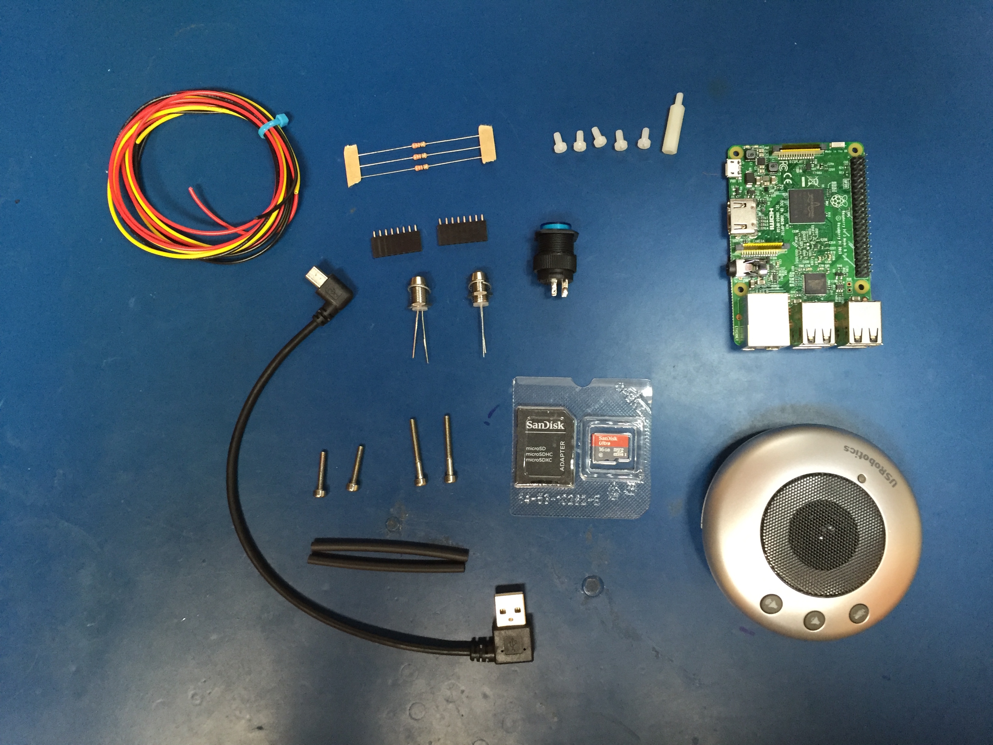\n\n* [Raspberry Pi 3 Model B ~$35](https://www.adafruit.com/products/3055)\n* [Micro SD Card](https://www.amazon.com/SanDisk-Ultra-Micro-Adapter-SDSQUNC-016G-GN6MA/dp/B010Q57SEE/ref=sr_1_3?ie=UTF8\u0026qid=1472828023\u0026sr=8-3\u0026keywords=16G+micro+sd+card)\n* [US Robotics USB Speakerphone (USR9610) between $4 and $12 (really cheap)](https://www.amazon.com/USRobotics-USB-Internet-Speakerphone-USR9610/dp/B000E6IL10/ref=sr_1_2?ie=UTF8\u0026qid=1472828042\u0026sr=8-2\u0026keywords=US+Robotics+usb+speakerphone)\n* [Short right angle / left angle mini USB cable](https://www.amazon.com/gp/product/B01CXT43MQ/ref=oh_aui_detailpage_o02_s00?ie=UTF8\u0026psc=1)\n* 5 x M3 nylon screws + 1 M3x20 nylon standoff\n* GPIO header connector (there are many options for this)\n* 2 x 5mm LEDs with [5mm LED holders](https://www.adafruit.com/products/2176)\n* [Pushbutton with LED](https://www.adafruit.com/product/1477)\n* 3 x 330ohm resistors\n* 2 x M3x15 + 2 x M3x25 stainless bolts (for the case)\n* 2 x M3x10 stainless bolts + nuts (for the speaker)\n* Hookup wire + heat-shrink\n\n---\n\n### The GPIO stuff\n\nThe GPIO interface usage is actually very simple. It is a push button with 2 separate LEDs for status indication and 1 LED within the push button that illuminates when it is transmitting.\n\n\n\nYou can use any type of header connector. I initially used [one of these](https://www.adafruit.com/product/2222), but using smaller connectors (such as a 8 pin for the LEDs and a 2 pin for the button) makes it easier to fit and assemble.\n\n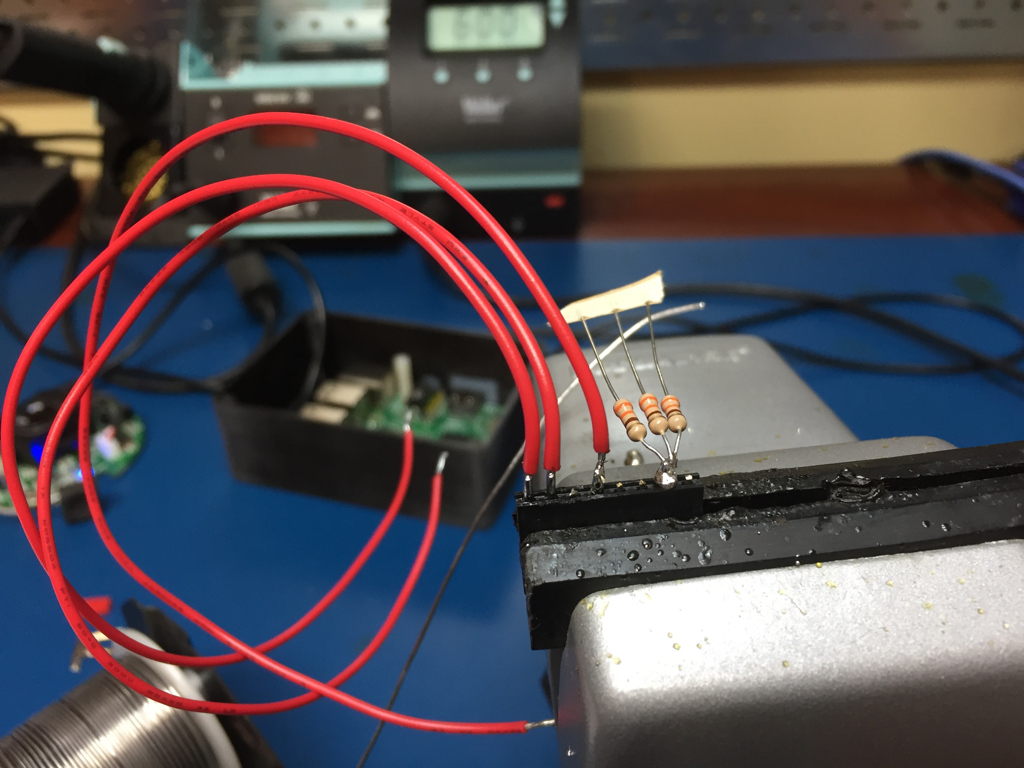\n\nSolder the 3 resistors to the ground pin, and solder your positive LED wires to the other pins.\n\n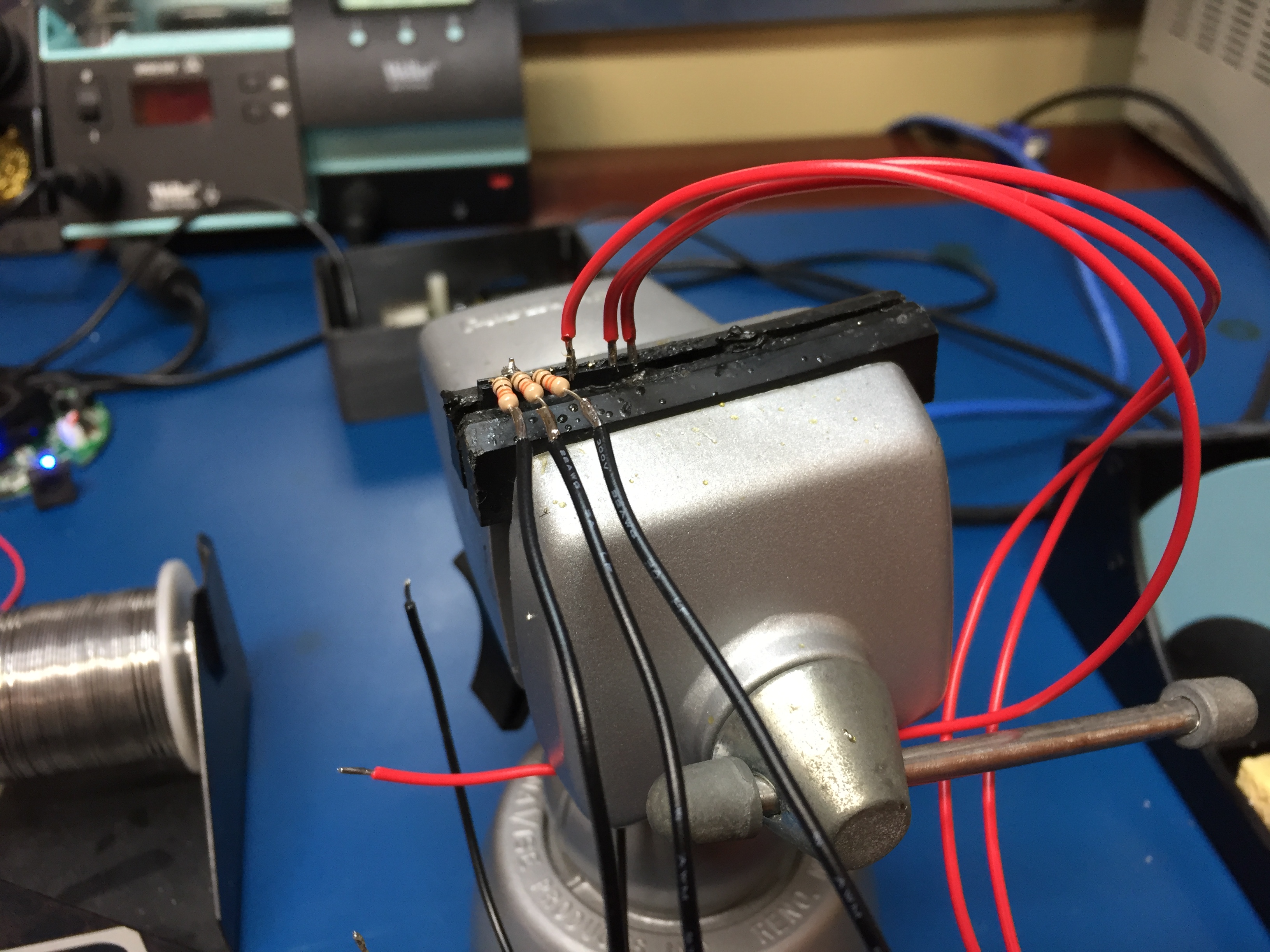\n\nSolder your negative LED wires to each of the resistors.\n\n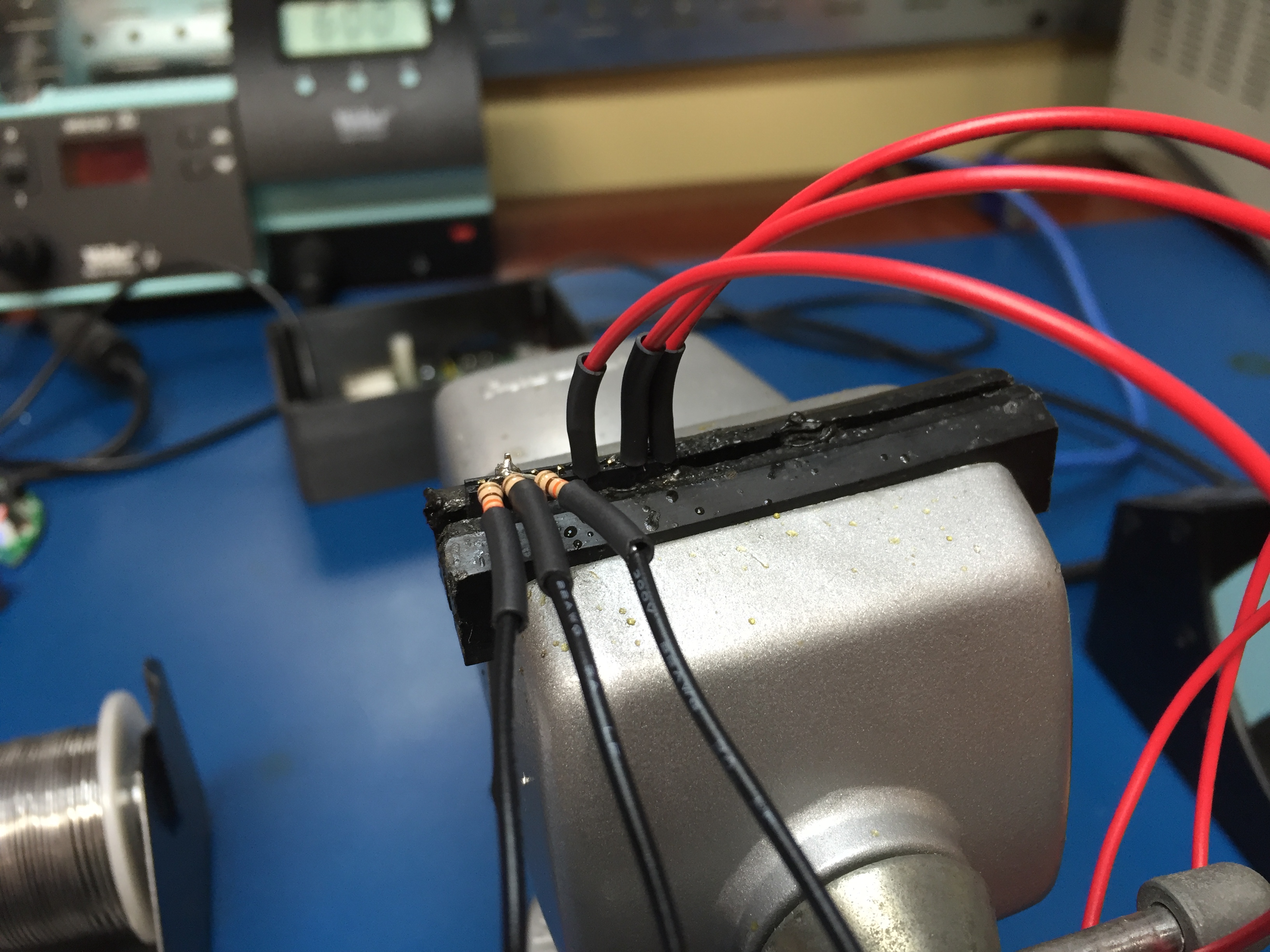\n\nSlip on heat-shrink to protect from shorting. I put a larger piece of heat-shrink around all the resistors to keep them in a nice solid bundle.\n\nNext up put together the button GPIO connector, you can either solder this on to your larger header, or like me, use a smaller 2 pin connector on pins 20 and 22.\n\nSolder the 2 status LEDs on to their respective leads. Don't forget to slip on the LED holder boots and the heat-shrink before you solder!\n\n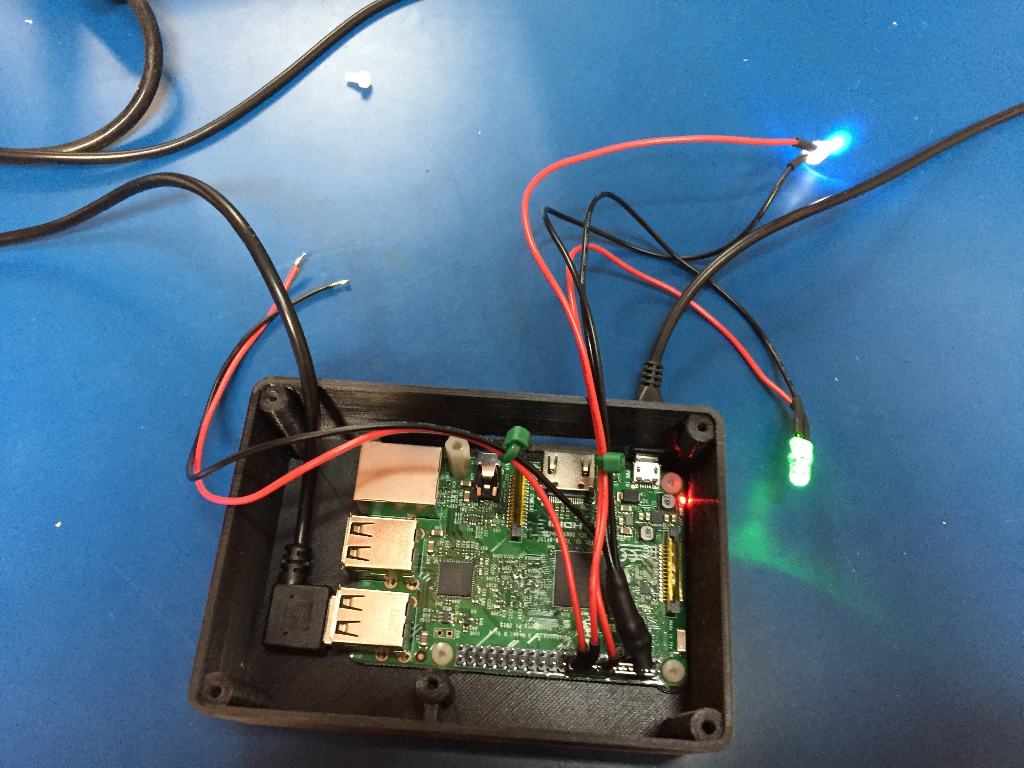\n\n---\n\n### The USB speakerphone\n\nTaking the speakerphone apart is really simple. There are two screws hiding under the rubber feet and two more screws holding the speaker in place.\n\n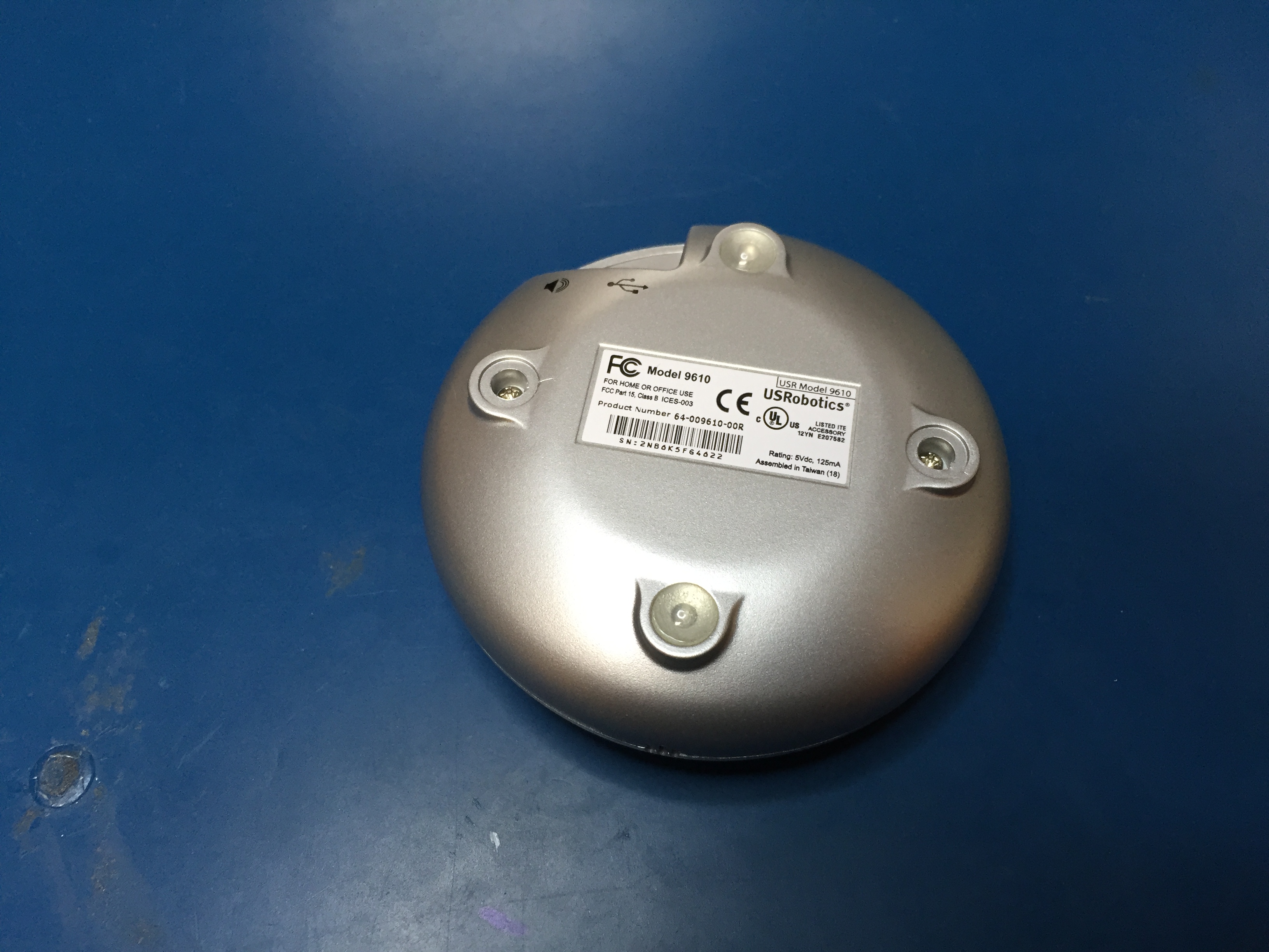\n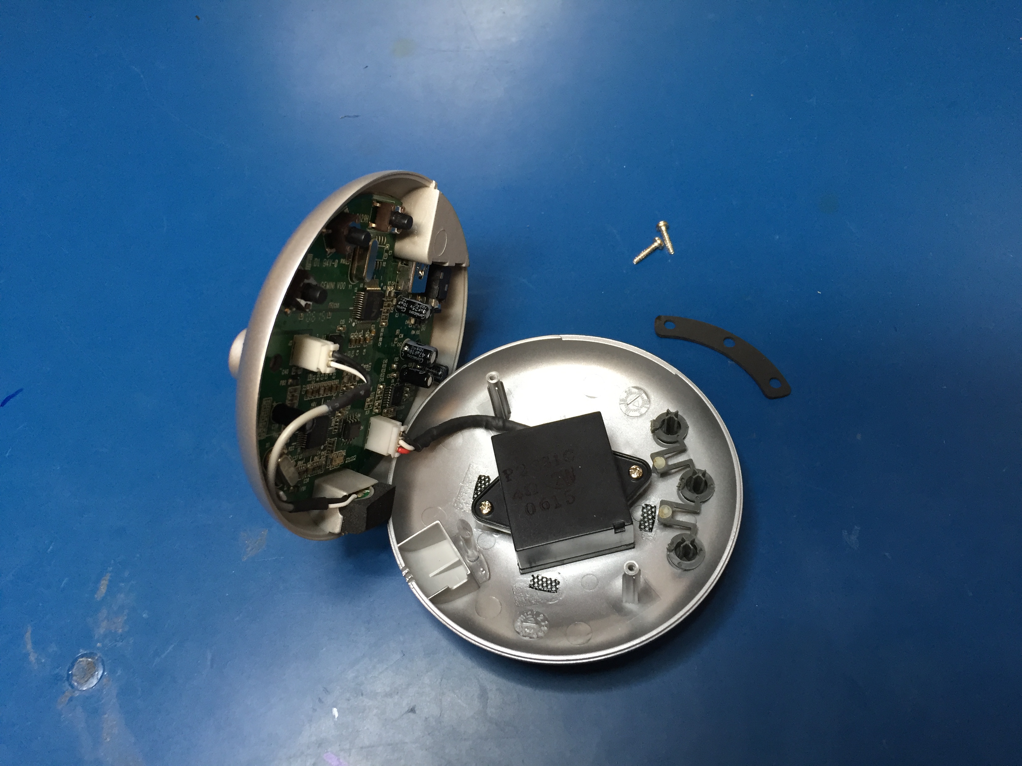\n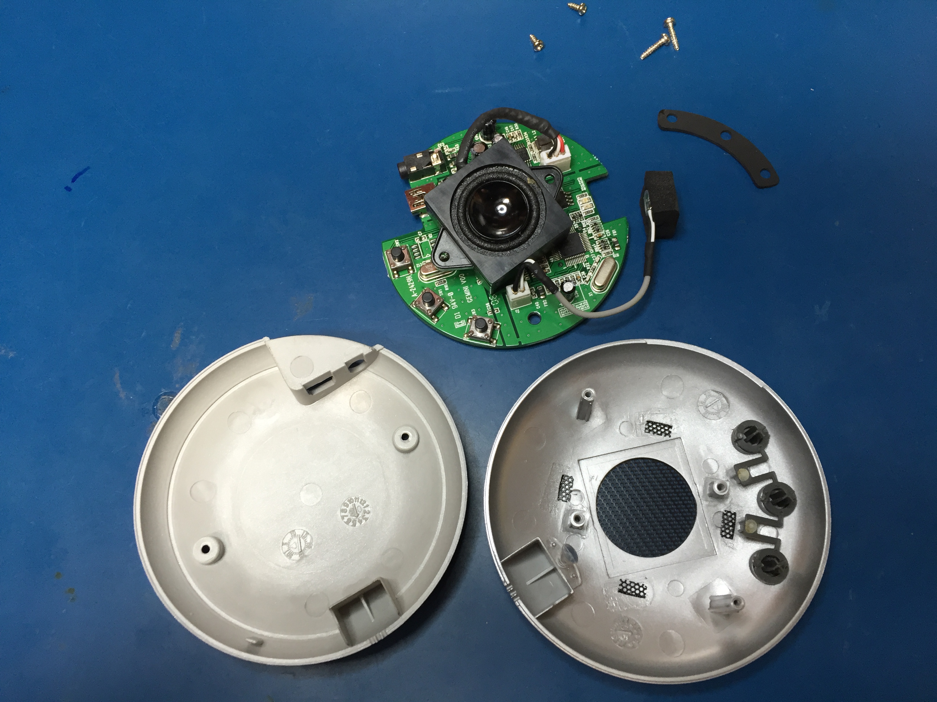\n\nLeave the foam on the microphone; the talkiepi case actually utilizes that to hold the microphone in place.\n\n\n### Assembling talkiepi\n\nI designed the enclosure to accommodate the Pi3 and the US Robotics speakerphone PCB specifically. Once you have printed the enclosure parts, I recommend you get a 3mm tap and tap the holes. If you don't have a tap, you can use one of your stainless bolts (carefully avoiding stripping out the holes).\n\n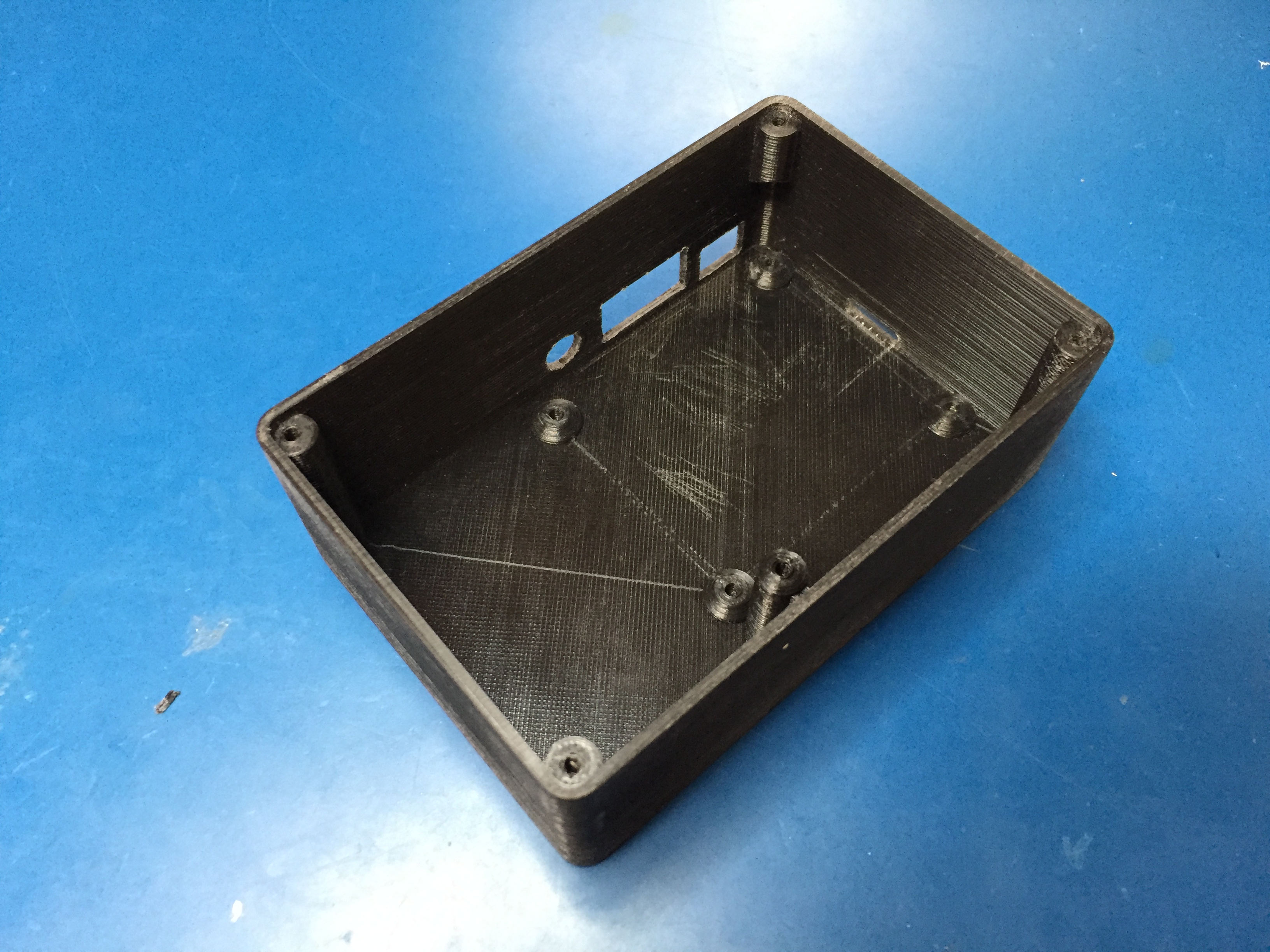\n\nAttach the right/left angle USB cable to the bottom right USB port of your Raspberry Pi. Mount the Raspberry Pi using the nylon screws. Use the standoff in the hole next to the 3.5mm audio jack.\n\n\n\nCarefully unclip and disconnect the speaker from the speakerphone PCB and mount the speaker on the front panel using your M3x10 bolts+nuts. You will likely need to drill out the holes on the speaker to 3mm. Connect your GPIO harness to the Raspberry Pi.\n\n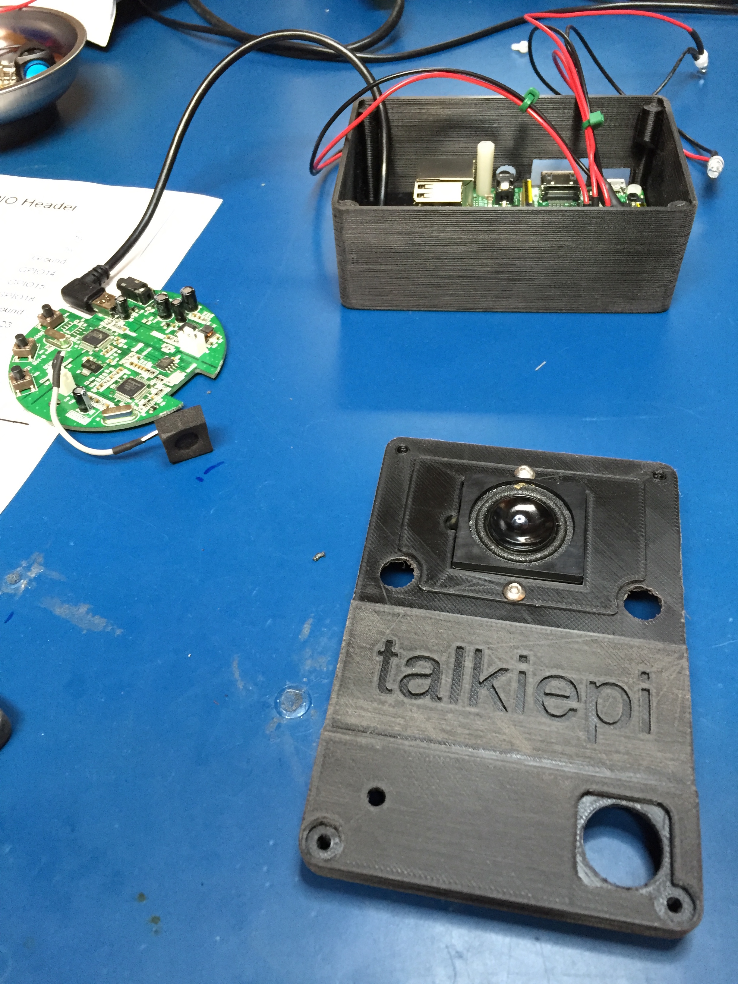\n\nPlace the LED holders through the speaker cover and place the speaker cover and LED holders through the top panel, fastening the LED holders in place with their washers and nuts. Secure the LED push button in place. \n\n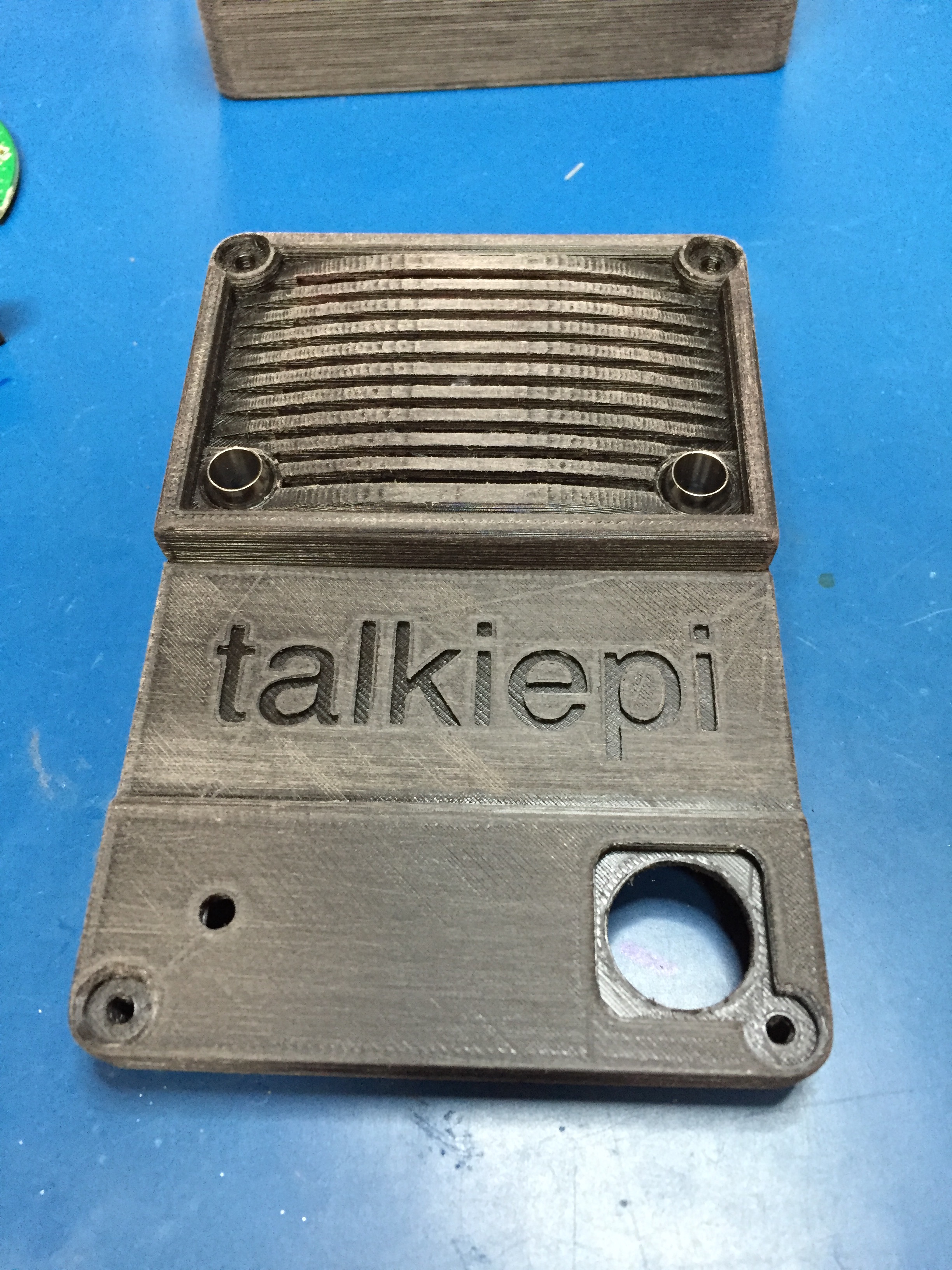\n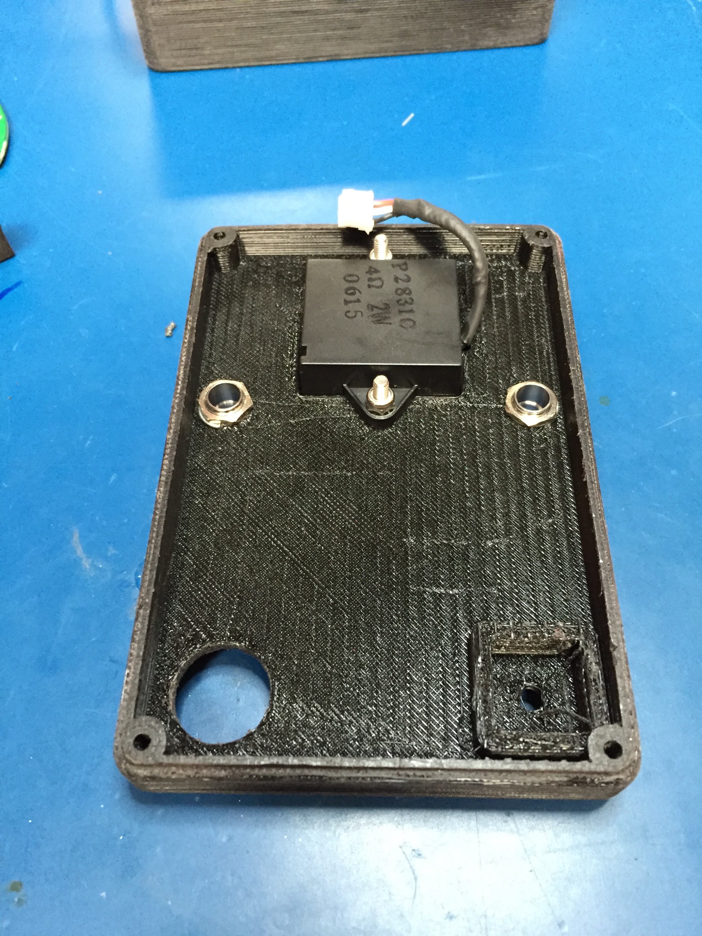\n\nNow slide the LEDs with boots into the LED holders (*I used a little bit of silicone sealant to ensure they dont push out*).\n\n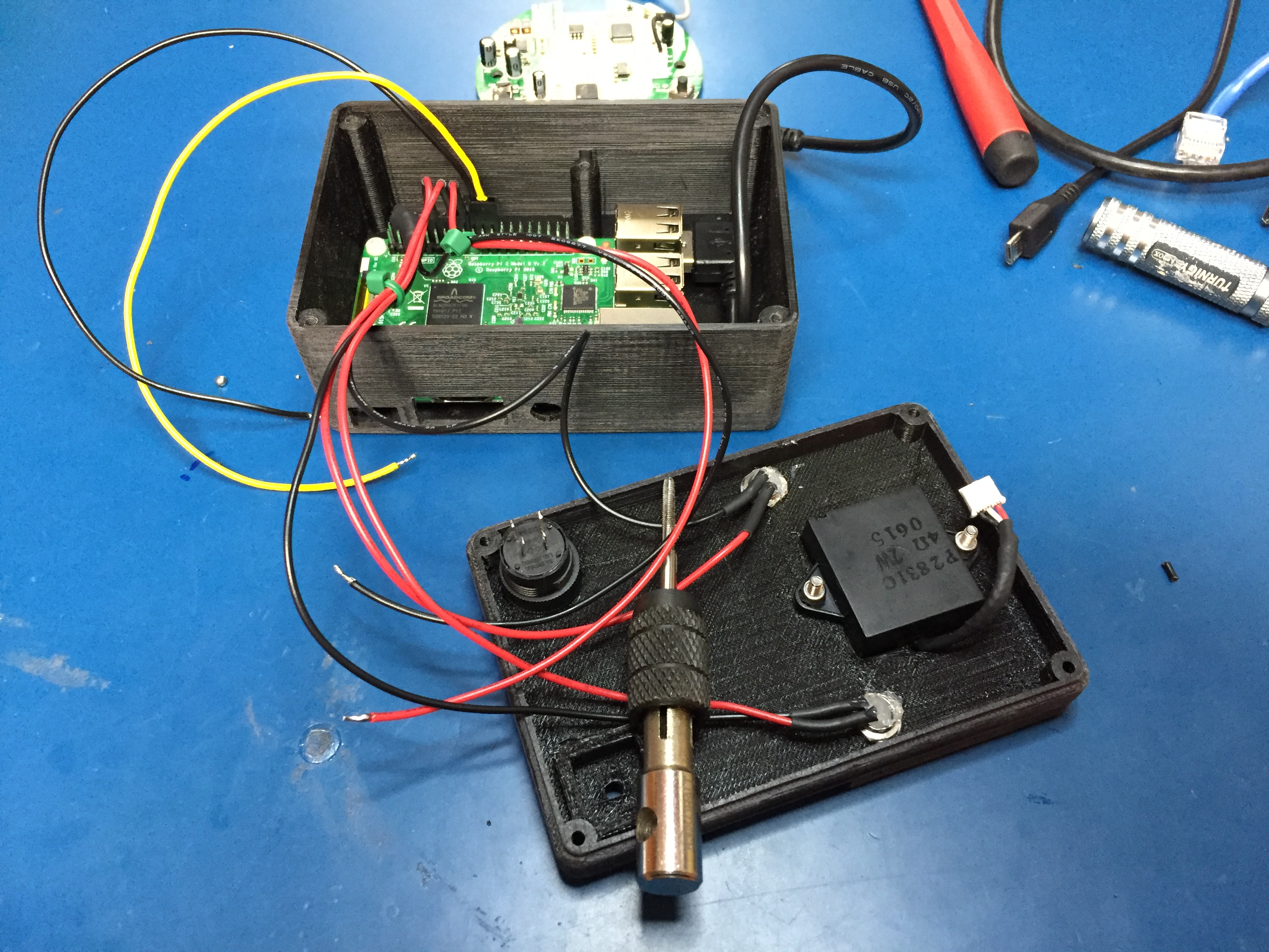\n\nNow mount the speakerphone PCB with the USB port facing towards the rear of the case (same direction as the Pi USB ports). Use the other two nylon screws to secure (one into the case and one into the standoff). Connect the USB cable to the speakerphone connector, folding/tucking the excess cable in the space behind the USB ports. Ensure your GPIO leads are routed cleanly around the speakerphone PCB, and that nothing could be shorting.\n\n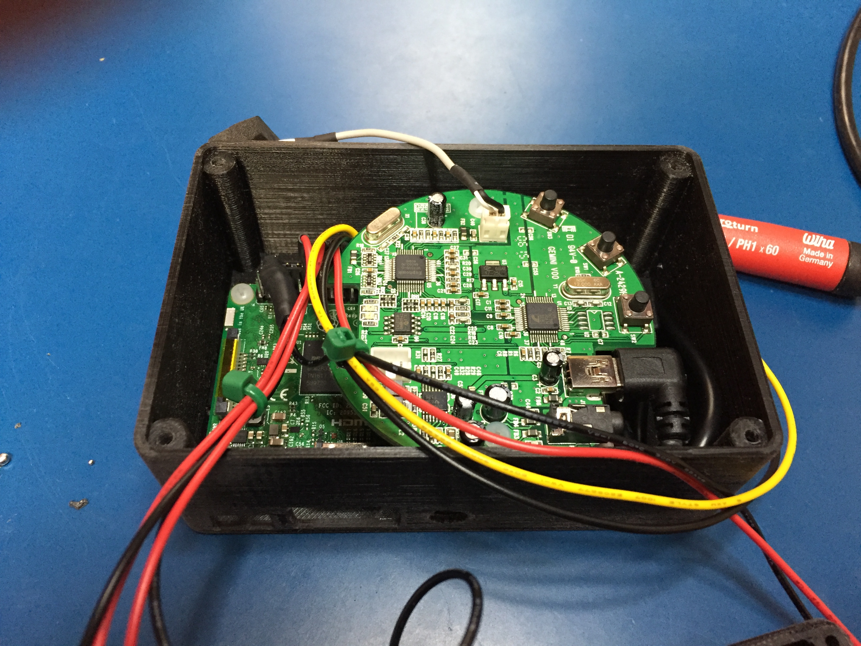\n\nFinally attach the top cover to the bottom. Be sure to feed the wires nicely, and that everything looks tucked out of the way inside. Again, check for any shorts before fastening the top with the M3 bolts.\n\n---\n\n### Enjoy your talkiepi!\n\nThats it! You're ready to talk to another mumble client or, if you made two, your other talkiepi!\n\n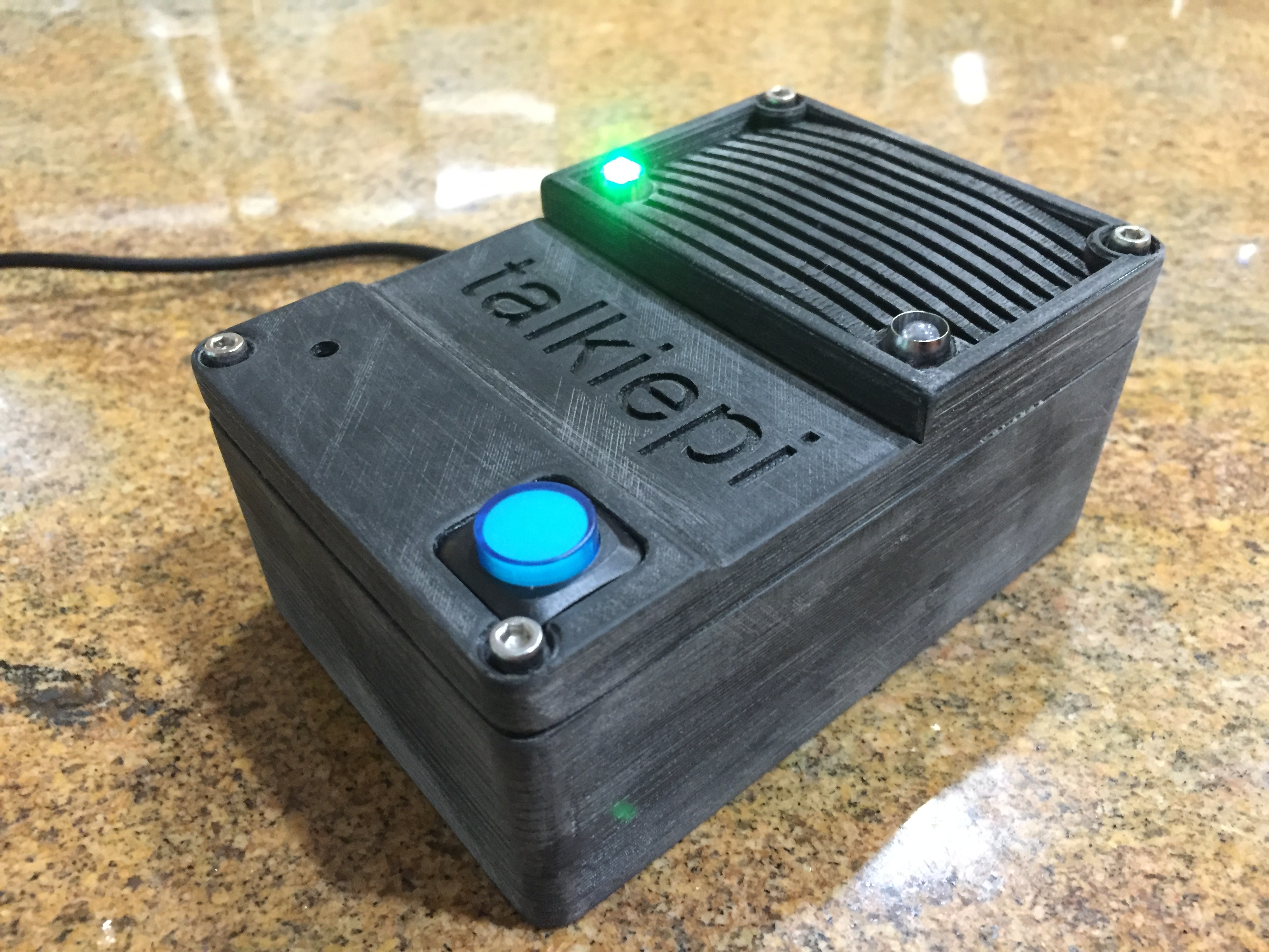\n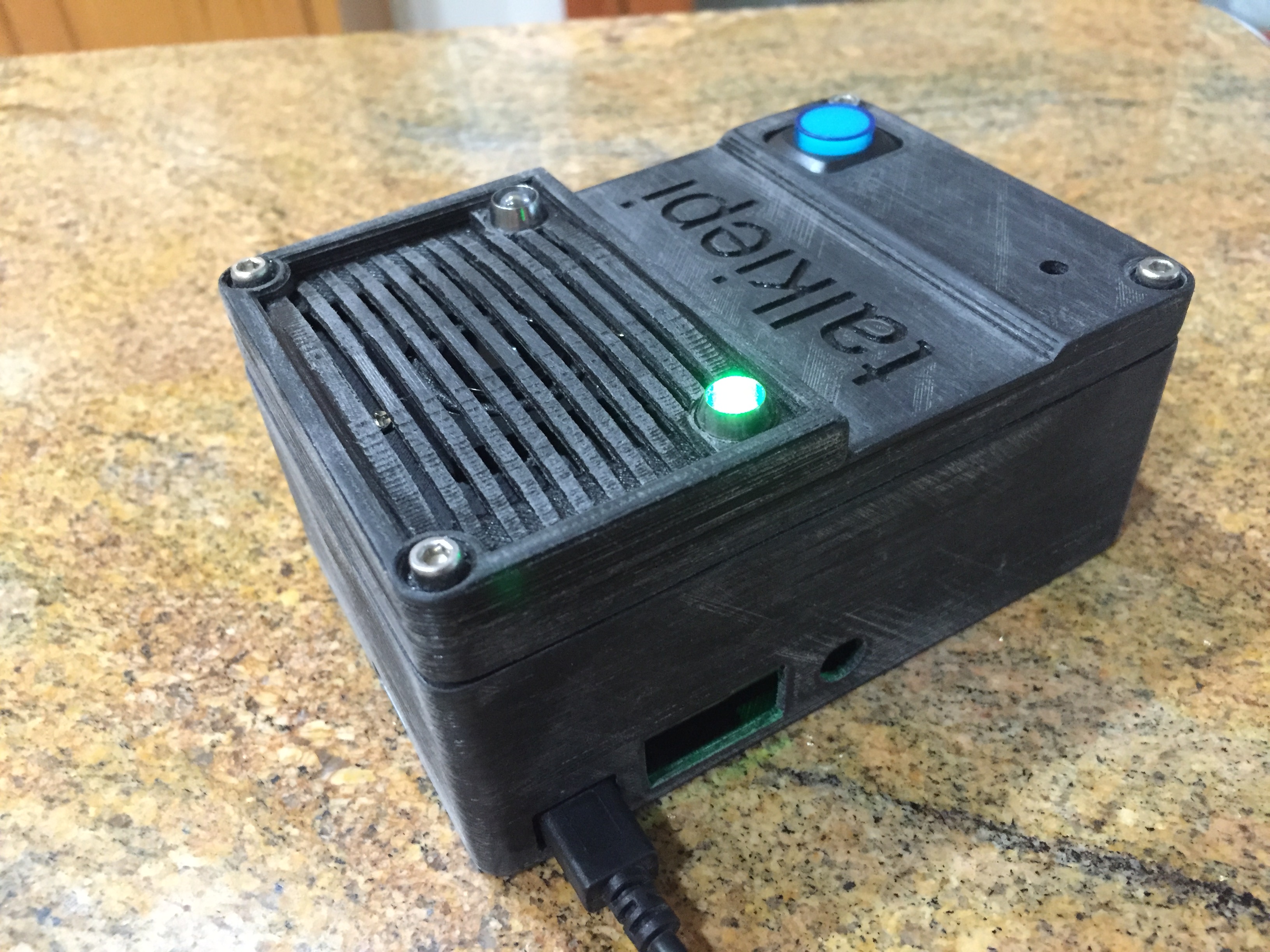\n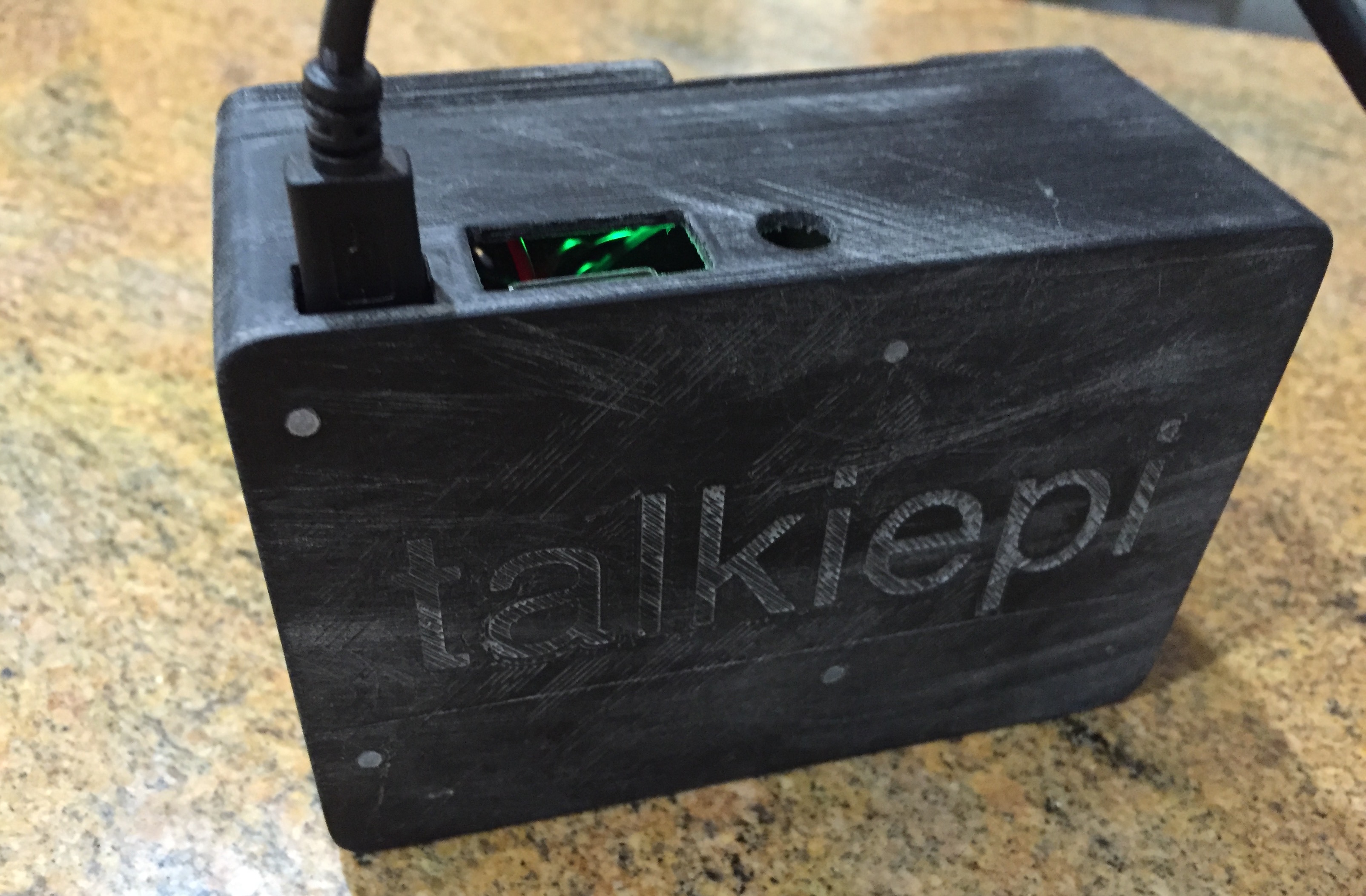\n\n\n---\n\n### Something different?\n\nI attempted to do a paint finish, but I just don't have the patience, or workspace to do a good job of spraying something this small. I do however have a bunch of different colored PLA. Check it out in blue and now red!\n\n\n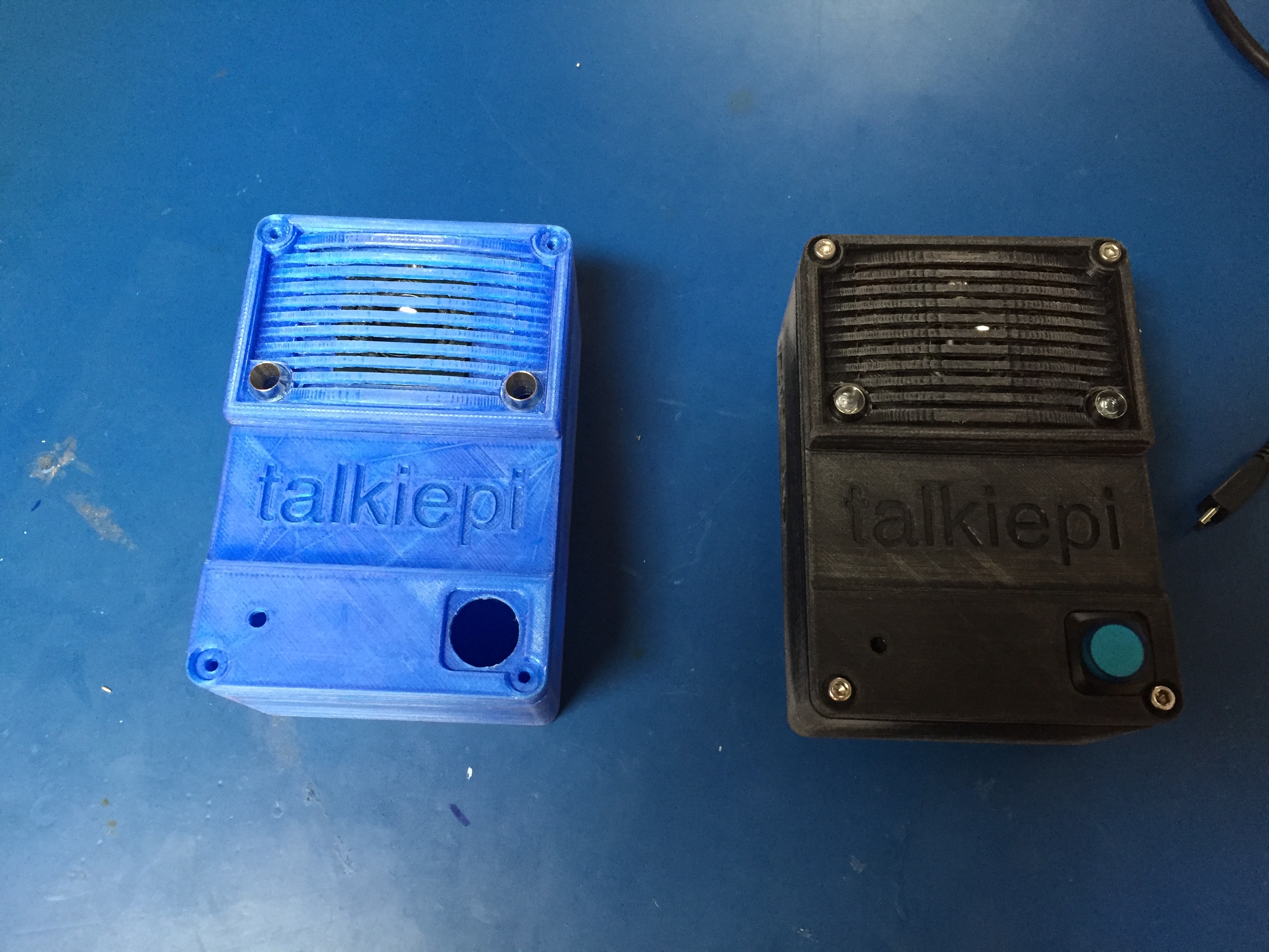\n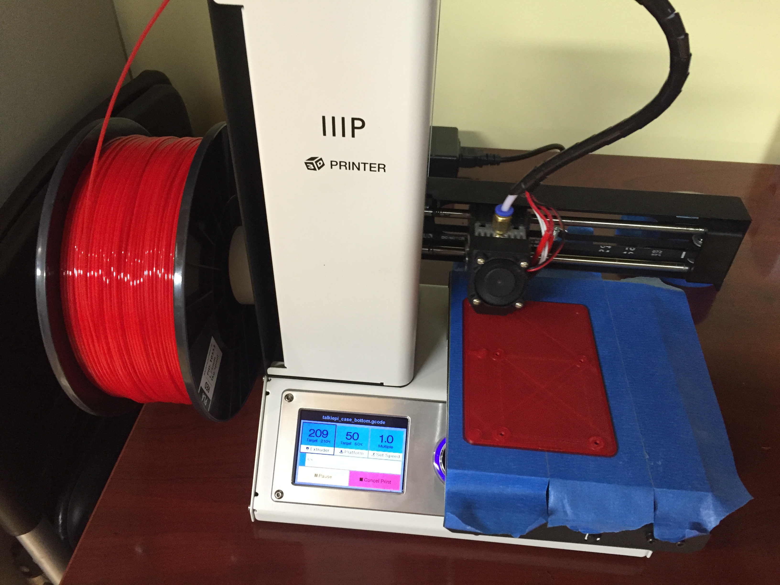\n\n\n### Whats next...\n\nI have a Raspberry Pi Zero, [HubPiWi](https://www.kickstarter.com/projects/1728237598/hubpiwi-raspberry-pi-zero-hub-with-wifi-no-cable-c), and a USB battery pack. \n\n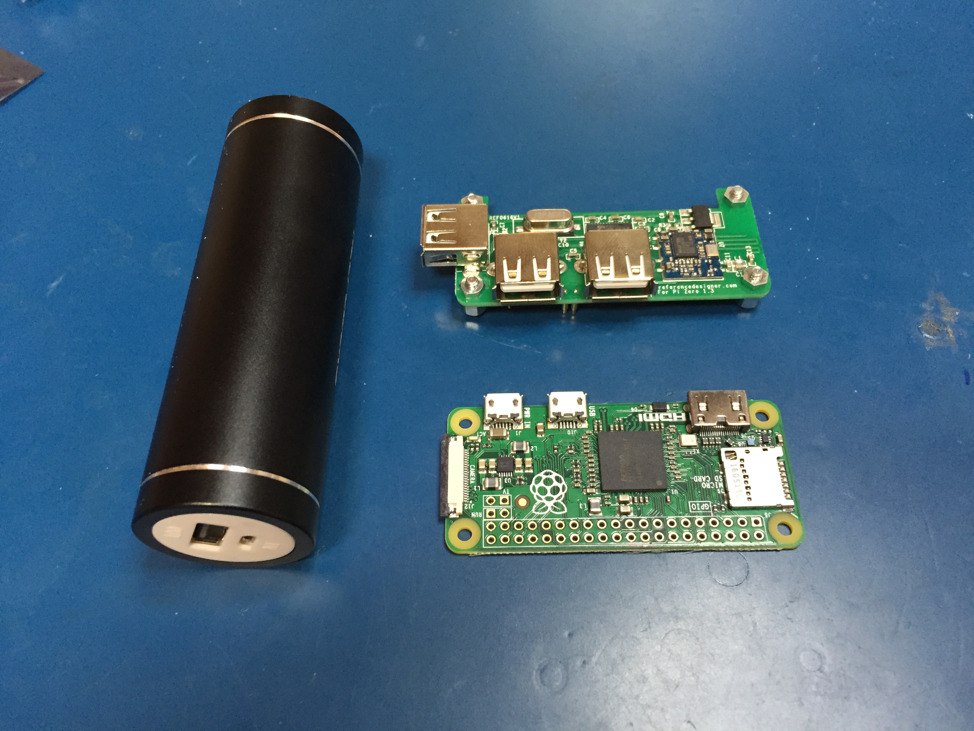\n\nI am going to attempt to build a much smaller and truly **walkie**, talkiepi. \n\nInitial testing and some minor code tweaks and talkiepi is running on a Raspberry Pi Zero with HubPiWi. \n\n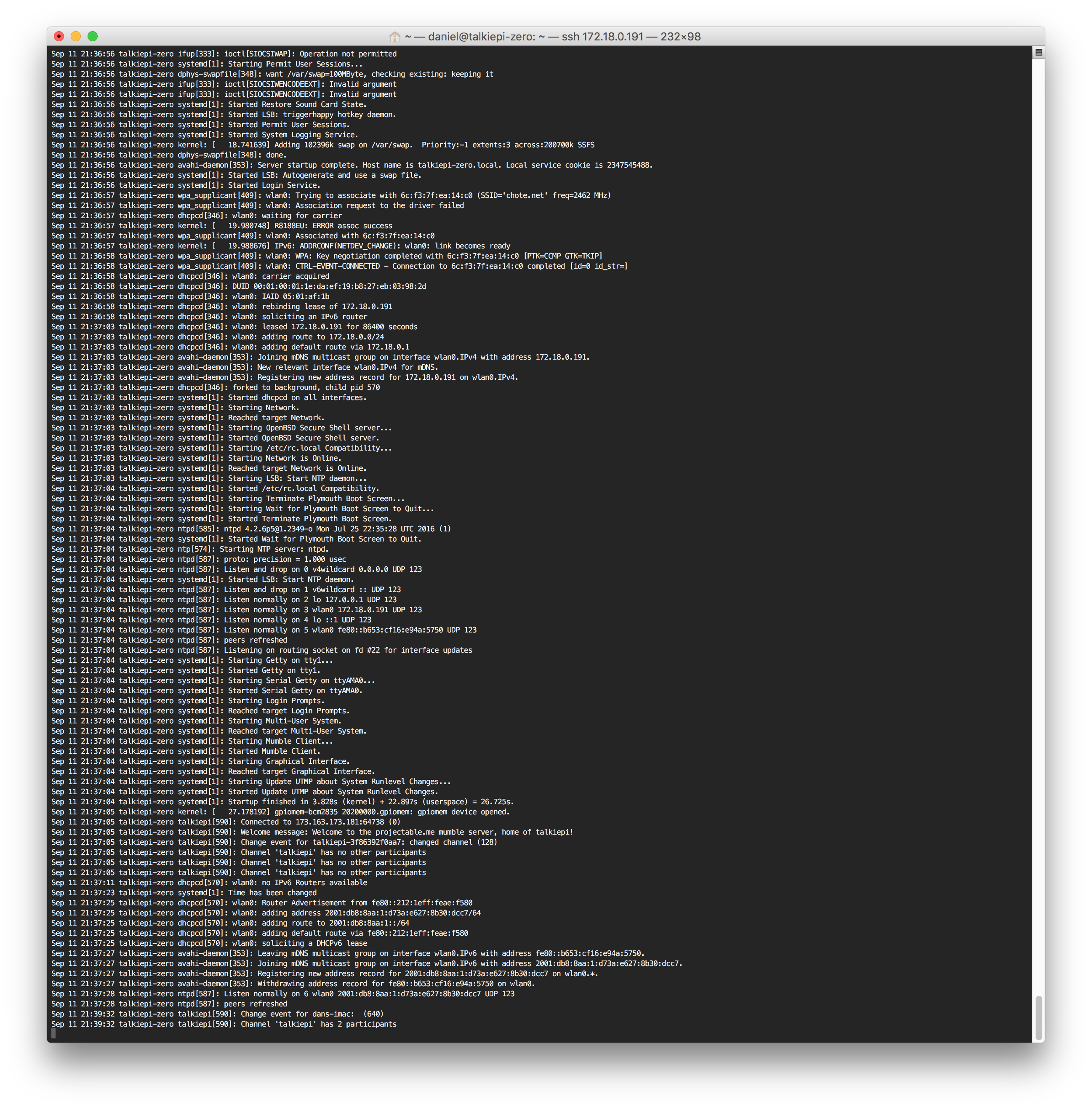\n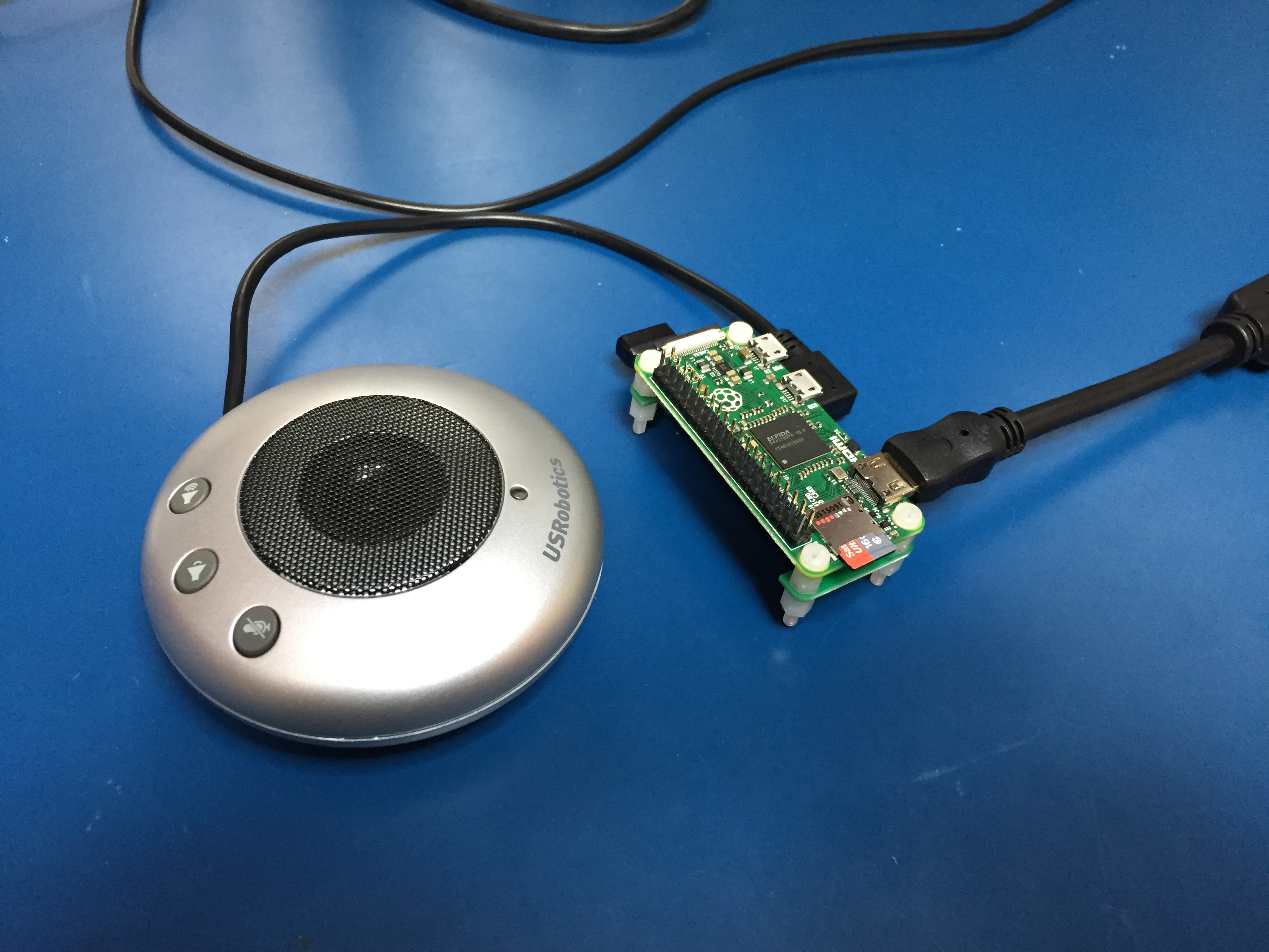\n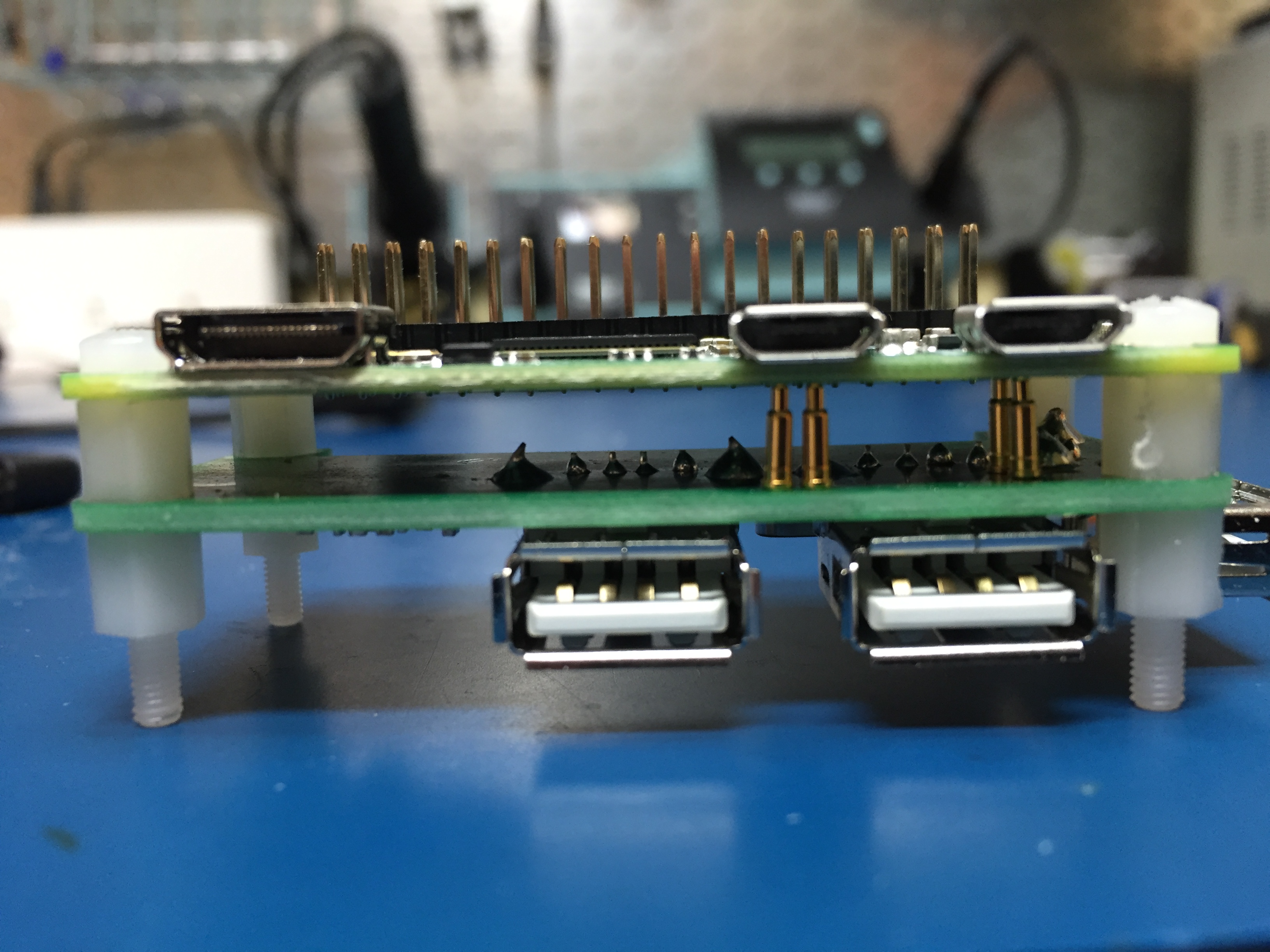\n\nOver the next few weeks I will be working on a new WALKIE talkiepi case design!\n\n**Stay tuned...**","html":"\u003ch2\u003eIntroducing \u003ca href=\"https://github.com/dchote/talkiepi\" rel=\"nofollow\"\u003etalkiepi\u003c/a\u003e\u003c/h2\u003e\n\u003cp\u003e\u003ca href=\"https://github.com/dchote/talkiepi\" rel=\"nofollow\"\u003etalkiepi\u003c/a\u003e is a wifi \u0026#34;walkie\u0026#34; talkie for your kids and their friends. It provides a very simple \u0026#34;push to talk\u0026#34; interface. When you push the button and talk, all the other talkiepis in the channel will hear what is being said.\u003c/p\u003e\n\u003cp\u003etalkiepi uses \u003ca href=\"http://mumble.info\" rel=\"nofollow\"\u003eMumble\u003c/a\u003e for its voice communication protocol. Mumble is an open source, lightweight, high quality voice chat system designed for use by PC gamers. Mumble lent itself perfectly for this use case. There are already software clients for all platforms (Mac, Win, Linux, IOS, Android), meaning you can talk with your talkiepi using your phone or computer, and you\u0026#39;re not limited to just talkiepi devices! By utilizing Mumble channels, user registration, and access control lists, you can configure different groups of talkiepis, just like using different channels on a traditional walkie talkie.\u003c/p\u003e\n\u003cp\u003e\u003ca href=\"https://github.com/dchote/talkiepi\" rel=\"nofollow\"\u003etalkiepi\u003c/a\u003e is built utilizing a \u003ca href=\"https://www.raspberrypi.org/products/raspberry-pi-3-model-b/\" rel=\"nofollow\"\u003eRaspberry Pi\u003c/a\u003e, \u003ca href=\"https://www.amazon.com/USRobotics-USB-Internet-Speakerphone-USR9610/dp/B000E6IL10\" rel=\"nofollow\"\u003eUSB speakerphone\u003c/a\u003e, some basic electronic components, and a 3D printed enclosure. \u003ca href=\"https://github.com/dchote/talkiepi\" rel=\"nofollow\"\u003etalkiepi\u003c/a\u003e runs a \u003ca href=\"http://mumble.info\" rel=\"nofollow\"\u003emumble\u003c/a\u003e \u003ca href=\"https://github.com/dchote/talkiepi\" rel=\"nofollow\"\u003eclient\u003c/a\u003e that has been designed specifically for push to talk via the push button interface. After it is setup on your wifi network and the software is configured, talkiepi will require little to no maintenance to use.\u003c/p\u003e\n\u003chr\u003e\n\u003ch3\u003etalkiepi software on your Raspberry Pi\u003c/h3\u003e\n\u003cp\u003eI have written an overview of the software and hardware interface at the \u003ca href=\"https://github.com/dchote/talkiepi\" rel=\"nofollow\"\u003egithub repository for talkiepi\u003c/a\u003e. An install guide can be found at \u003ca href=\"https://github.com/dchote/talkiepi/blob/master/doc/README.md\" rel=\"nofollow\"\u003ehttps://github.com/dchote/talkiepi/blob/master/doc/README.md\u003c/a\u003e, which will step you through installing talkiepi on your Raspberry Pi.\u003c/p\u003e\n\u003cp\u003e\u003cem\u003eOn September 10th there was a pull request against the go-openal library that broke things on Raspbian Jessie, I have since forked the library and reverted the changes. talkiepi now uses my fork of the library and should now build again\u003c/em\u003e\u003c/p\u003e\n\u003cp\u003eI have added some notes regarding my wifi trouble on the rpi3 \u003ca href=\"http://projectable.me/optimize-my-pi-wi-fi/\" rel=\"nofollow\"\u003ehere\u003c/a\u003e.\u003c/p\u003e\n\u003chr\u003e\n\u003ch3\u003eBuilding a talkiepi\u003c/h3\u003e\n\u003ch5\u003eBuild without an enclosure:\u003c/h5\u003e\n\u003cp\u003eYou can assemble a talkiepi with or without the 3D printed enclosure. I initially prototyped the GPIO stuff on a breadboard, and that would be more than sufficient to play with if you didn\u0026#39;t want to commit to a full build.\u003c/p\u003e\n\u003cimg src=\"/content/images/2016/09/IMG_8844.JPG\" alt=\"breadboard\"\u003e\n\u003ch5\u003ePrint an enclosure:\u003c/h5\u003e\n\u003cp\u003eIf you want to do a full build of talkiepi you can download the 3D models from the \u003ca href=\"https://github.com/dchote/talkiepi/tree/master/stl\" rel=\"nofollow\"\u003egithub repository\u003c/a\u003e. I printed my parts on my \u003ca href=\"http://www.monoprice.com/product?p_id=15365\" rel=\"nofollow\"\u003eMonoprice Select Mini 3D Printer\u003c/a\u003e. I printed in PLA with 100% infill. You \u003cem\u003ewill\u003c/em\u003e need to rotate the models to print, but if you already have a 3D printer, you probably know what you need to do. If you don\u0026#39;t own a 3D printer yet, there are many services that will print and mail you your parts!\u003c/p\u003e\n\u003cp\u003eI designed the talkiepi enclosure in Autodesk\u0026#39;s \u003ca href=\"http://www.autodesk.com/products/fusion-360/overview\" rel=\"nofollow\"\u003eFusion360\u003c/a\u003e. If anyone would like to tweak the Fusion360 assembly, drop me a tweet \u003ca href=\"https://http://twitter.com/dchote/\" rel=\"nofollow\"\u003e@dchote\u003c/a\u003e #talkiepi.\u003c/p\u003e\n\u003cimg src=\"/content/images/2016/09/14195449_10154470917845419_4831834876665870570_o.jpg\" alt=\"fusion360\"\u003e\n\u003cimg src=\"/content/images/2016/09/IMG_8946-1.JPG\" alt=\"\"\u003e\n\u003cimg src=\"/content/images/2016/09/IMG_8947.JPG\" alt=\"\"\u003e\n\u003cimg src=\"/content/images/2016/09/IMG_8939.JPG\" alt=\"\"\u003e\n\u003chr\u003e\n\u003ch3\u003etalkiepi parts\u003c/h3\u003e\n\u003cp\u003eI ordered most of these components from \u003ca href=\"https://www.adafruit.com\" rel=\"nofollow\"\u003eAdafruit\u003c/a\u003e, and a couple of parts from \u003ca href=\"https://www.amazon.com\" rel=\"nofollow\"\u003eAmazon.com\u003c/a\u003e. I already had the hookup wire, heat-shrink and resistors.\u003c/p\u003e\n\u003cimg src=\"/content/images/2016/09/IMG_8933.JPG\" alt=\"talkiepi parts\"\u003e\n\u003cul\u003e\n\u003cli\u003e\u003ca href=\"https://www.adafruit.com/products/3055\" rel=\"nofollow\"\u003eRaspberry Pi 3 Model B ~$35\u003c/a\u003e\u003c/li\u003e\n\u003cli\u003e\u003ca href=\"https://www.amazon.com/SanDisk-Ultra-Micro-Adapter-SDSQUNC-016G-GN6MA/dp/B010Q57SEE/ref=sr_1_3?ie=UTF8\u0026amp;qid=1472828023\u0026amp;sr=8-3\u0026amp;keywords=16G+micro+sd+card\" rel=\"nofollow\"\u003eMicro SD Card\u003c/a\u003e\u003c/li\u003e\n\u003cli\u003e\u003ca href=\"https://www.amazon.com/USRobotics-USB-Internet-Speakerphone-USR9610/dp/B000E6IL10/ref=sr_1_2?ie=UTF8\u0026amp;qid=1472828042\u0026amp;sr=8-2\u0026amp;keywords=US+Robotics+usb+speakerphone\" rel=\"nofollow\"\u003eUS Robotics USB Speakerphone (USR9610) between $4 and $12 (really cheap)\u003c/a\u003e\u003c/li\u003e\n\u003cli\u003e\u003ca href=\"https://www.amazon.com/gp/product/B01CXT43MQ/ref=oh_aui_detailpage_o02_s00?ie=UTF8\u0026amp;psc=1\" rel=\"nofollow\"\u003eShort right angle / left angle mini USB cable\u003c/a\u003e\u003c/li\u003e\n\u003cli\u003e5 x M3 nylon screws + 1 M3x20 nylon standoff\u003c/li\u003e\n\u003cli\u003eGPIO header connector (there are many options for this)\u003c/li\u003e\n\u003cli\u003e2 x 5mm LEDs with \u003ca href=\"https://www.adafruit.com/products/2176\" rel=\"nofollow\"\u003e5mm LED holders\u003c/a\u003e\u003c/li\u003e\n\u003cli\u003e\u003ca href=\"https://www.adafruit.com/product/1477\" rel=\"nofollow\"\u003ePushbutton with LED\u003c/a\u003e\u003c/li\u003e\n\u003cli\u003e3 x 330ohm resistors\u003c/li\u003e\n\u003cli\u003e2 x M3x15 + 2 x M3x25 stainless bolts (for the case)\u003c/li\u003e\n\u003cli\u003e2 x M3x10 stainless bolts + nuts (for the speaker)\u003c/li\u003e\n\u003cli\u003eHookup wire + heat-shrink\u003c/li\u003e\n\u003c/ul\u003e\n\u003chr\u003e\n\u003ch3\u003eThe GPIO stuff\u003c/h3\u003e\n\u003cp\u003eThe GPIO interface usage is actually very simple. It is a push button with 2 separate LEDs for status indication and 1 LED within the push button that illuminates when it is transmitting.\u003c/p\u003e\n\u003cimg src=\"https://github.com/dchote/talkiepi/raw/master/doc/gpio_diagram.png\" alt=\"\"\u003e\n\u003cp\u003eYou can use any type of header connector. I initially used \u003ca href=\"https://www.adafruit.com/product/2222\" rel=\"nofollow\"\u003eone of these\u003c/a\u003e, but using smaller connectors (such as a 8 pin for the LEDs and a 2 pin for the button) makes it easier to fit and assemble.\u003c/p\u003e\n\u003cimg src=\"/content/images/2016/09/IMG_8958.JPG\" alt=\"\"\u003e\n\u003cp\u003eSolder the 3 resistors to the ground pin, and solder your positive LED wires to the other pins.\u003c/p\u003e\n\u003cimg src=\"/content/images/2016/09/IMG_8959.JPG\" alt=\"\"\u003e\n\u003cp\u003eSolder your negative LED wires to each of the resistors.\u003c/p\u003e\n\u003cimg src=\"/content/images/2016/09/IMG_8960.JPG\" alt=\"\"\u003e\n\u003cp\u003eSlip on heat-shrink to protect from shorting. I put a larger piece of heat-shrink around all the resistors to keep them in a nice solid bundle.\u003c/p\u003e\n\u003cp\u003eNext up put together the button GPIO connector, you can either solder this on to your larger header, or like me, use a smaller 2 pin connector on pins 20 and 22.\u003c/p\u003e\n\u003cp\u003eSolder the 2 status LEDs on to their respective leads. Don\u0026#39;t forget to slip on the LED holder boots and the heat-shrink before you solder!\u003c/p\u003e\n\u003cimg src=\"/content/images/2016/09/IMG_8962.JPG\" alt=\"\"\u003e\n\u003chr\u003e\n\u003ch3\u003eThe USB speakerphone\u003c/h3\u003e\n\u003cp\u003eTaking the speakerphone apart is really simple. There are two screws hiding under the rubber feet and two more screws holding the speaker in place.\u003c/p\u003e\n\u003cimg src=\"/content/images/2016/09/IMG_8935.JPG\" alt=\"\"\u003e\n\u003cimg src=\"/content/images/2016/09/IMG_8936.JPG\" alt=\"\"\u003e\n\u003cimg src=\"/content/images/2016/09/IMG_8937.JPG\" alt=\"\"\u003e\n\u003cp\u003eLeave the foam on the microphone; the talkiepi case actually utilizes that to hold the microphone in place.\u003c/p\u003e\n\u003ch3\u003eAssembling talkiepi\u003c/h3\u003e\n\u003cp\u003eI designed the enclosure to accommodate the Pi3 and the US Robotics speakerphone PCB specifically. Once you have printed the enclosure parts, I recommend you get a 3mm tap and tap the holes. If you don\u0026#39;t have a tap, you can use one of your stainless bolts (carefully avoiding stripping out the holes).\u003c/p\u003e\n\u003cimg src=\"/content/images/2016/09/IMG_8940.JPG\" alt=\"\"\u003e\n\u003cp\u003eAttach the right/left angle USB cable to the bottom right USB port of your Raspberry Pi. Mount the Raspberry Pi using the nylon screws. Use the standoff in the hole next to the 3.5mm audio jack.\u003c/p\u003e\n\u003cimg src=\"/content/images/2016/09/IMG_8872.JPG\" alt=\"\"\u003e\n\u003cp\u003eCarefully unclip and disconnect the speaker from the speakerphone PCB and mount the speaker on the front panel using your M3x10 bolts+nuts. You will likely need to drill out the holes on the speaker to 3mm. Connect your GPIO harness to the Raspberry Pi.\u003c/p\u003e\n\u003cimg src=\"/content/images/2016/09/IMG_8963-1.JPG\" alt=\"\"\u003e\n\u003cp\u003ePlace the LED holders through the speaker cover and place the speaker cover and LED holders through the top panel, fastening the LED holders in place with their washers and nuts. Secure the LED push button in place.\u003c/p\u003e\n\u003cimg src=\"/content/images/2016/09/IMG_8964-1.JPG\" alt=\"\"\u003e\n\u003cimg src=\"/content/images/2016/09/IMG_8965-1.JPG\" alt=\"\"\u003e\n\u003cp\u003eNow slide the LEDs with boots into the LED holders (\u003cem\u003eI used a little bit of silicone sealant to ensure they dont push out\u003c/em\u003e).\u003c/p\u003e\n\u003cimg src=\"/content/images/2016/09/IMG_8968.JPG\" alt=\"\"\u003e\n\u003cp\u003eNow mount the speakerphone PCB with the USB port facing towards the rear of the case (same direction as the Pi USB ports). Use the other two nylon screws to secure (one into the case and one into the standoff). Connect the USB cable to the speakerphone connector, folding/tucking the excess cable in the space behind the USB ports. Ensure your GPIO leads are routed cleanly around the speakerphone PCB, and that nothing could be shorting.\u003c/p\u003e\n\u003cimg src=\"/content/images/2016/09/IMG_8969.JPG\" alt=\"\"\u003e\n\u003cp\u003eFinally attach the top cover to the bottom. Be sure to feed the wires nicely, and that everything looks tucked out of the way inside. Again, check for any shorts before fastening the top with the M3 bolts.\u003c/p\u003e\n\u003chr\u003e\n\u003ch3\u003eEnjoy your talkiepi!\u003c/h3\u003e\n\u003cp\u003eThats it! You\u0026#39;re ready to talk to another mumble client or, if you made two, your other talkiepi!\u003c/p\u003e\n\u003cimg src=\"/content/images/2016/09/IMG_8925-2.JPG\" alt=\"\"\u003e\n\u003cimg src=\"/content/images/2016/09/IMG_8926.JPG\" alt=\"\"\u003e\n\u003cimg src=\"/content/images/2016/09/IMG_8927-1.JPG\" alt=\"\"\u003e\n\u003chr\u003e\n\u003ch3\u003eSomething different?\u003c/h3\u003e\n\u003cp\u003eI attempted to do a paint finish, but I just don\u0026#39;t have the patience, or workspace to do a good job of spraying something this small. I do however have a bunch of different colored PLA. Check it out in blue and now red!\u003c/p\u003e\n\u003cimg src=\"/content/images/2016/09/IMG_8978.JPG\" alt=\"\"\u003e\n\u003cimg src=\"/content/images/2016/09/IMG_8979.JPG\" alt=\"\"\u003e\n\u003cimg src=\"/content/images/2016/09/IMG_8993.JPG\" alt=\"\"\u003e\n\u003ch3\u003eWhats next...\u003c/h3\u003e\n\u003cp\u003eI have a Raspberry Pi Zero, \u003ca href=\"https://www.kickstarter.com/projects/1728237598/hubpiwi-raspberry-pi-zero-hub-with-wifi-no-cable-c\" rel=\"nofollow\"\u003eHubPiWi\u003c/a\u003e, and a USB battery pack.\u003c/p\u003e\n\u003cimg src=\"/content/images/2016/09/IMG_8994.JPG\" alt=\"\"\u003e\n\u003cp\u003eI am going to attempt to build a much smaller and truly \u003cstrong\u003ewalkie\u003c/strong\u003e, talkiepi.\u003c/p\u003e\n\u003cp\u003eInitial testing and some minor code tweaks and talkiepi is running on a Raspberry Pi Zero with HubPiWi.\u003c/p\u003e\n\u003cimg src=\"/content/images/2016/09/Screen-Shot-2016-09-11-at-9-40-11-PM.png\" alt=\"\"\u003e\n\u003cimg src=\"/content/images/2016/09/IMG_9013.JPG\" alt=\"\"\u003e\n\u003cimg src=\"/content/images/2016/09/IMG_9011.JPG\" alt=\"\"\u003e\n\u003cp\u003eOver the next few weeks I will be working on a new WALKIE talkiepi case design!\u003c/p\u003e\n\u003cp\u003e\u003cstrong\u003eStay tuned...\u003c/strong\u003e\u003c/p\u003e\n","excerpt":"","metaTitle":"","metaDescription":"","status":"published","featured":false,"publishedAt":"2016-09-02T16:13:39Z","authorId":"190160de54f2192bd5b8734ec8808086","authorName":"Daniel Chote","authorSlug":"daniel","heroMediaId":"","projectId":"","tags":[{"id":"b529314e428273696b02c474dcf56132","name":"Raspberry Pi","slug":"raspberry-pi"},{"id":"b223b3e2ba0e78e7e6a6a8ff4349517d","name":"talkiepi","slug":"talkiepi"},{"id":"e2e48067ff28749272dbdc37a0f2023d","name":"golang","slug":"golang"}],"createdAt":"2026-10-18T13:16:27Z","updatedAt":"2026-10-18T13:16:27Z"},{"id":"5c6c6c8242f9d3e5e6550eef9bddccaf","siteId":"projectable","slug":"building-an-internet-walkie-talkie-using-a-raspberry-pi-v3","title":"Building an Internet Walkie Talkie using a Raspberry Pi v3","markdown":"###Introducing [talkiepi](https://github.com/dchote/talkiepi).\n\n**New post: http://projectable.me/i-built-a-wifi-walkie-talkie-for-my-kids-now-you-can-too/**\n\nIve had this idea for a VERY long time, to build a relatively cost effective, kid friendly, internet enabled walkie talkie. It has to be as simple as an oldschool walkie talkie to use, but it should run over wifi and allow kids to communicate with their friends in a simple and reliable way.\n\nI recently came across a commandline mumble client written in go, called [Barnard](https://github.com/layeh/barnard). When I tested it, it seemed to do the job, so this weekend I ran with it and created [talkiepi](https://github.com/dchote/talkiepi). \n\nThe biggest hurdle I had was finding a GPIO library that worked for my use case, and worked inside the existing barnard codebase. My initial digging with [go-rpio](https://github.com/stianeikeland/go-rpio) was a huge headache of crashes that shouldnt happen. So I decided to go the sysfs route and settled on a slight modification to [Brian Armstrong's](https://github.com/brian-armstrong/gpio) [go GPIO library](https://github.com/dchote/gpio). After getting this working I realized I still had to enable the internal pullup on the button pin, so I went back to using [go-rpio](https://github.com/stianeikeland/go-rpio) for just that.\n\nI managed to fix the bug that stopped audio from sending when you press the button the second time. talkiepi is now fully functional! I will be working on some cleanup and housekeeping stuff (such as config files) next.\n\n____\n\n###Try it yourself!\nYou can play with it on your pi and see how it goes, I do recommend using the latest raspbian image though.\n\nFirst install the required raspbian packages `apt-get install golang libopenal-dev libopus-dev`. Once installed setup your `GOPATH`. I recommend creating a directory in your home called `gocode`, then `export GOPATH=$HOME/gocode`. You can add that to your .profile to persist it for future logins etc.\n\nChange to your new directory `cd $GOPATH` and then run the following:\n```\ngo get github.com/layeh/gopus\ngo get github.com/dchote/talkiepi\n```\n\nNow you can jump in to the code and run it:\n```\ncd $GOPATH/src/github.com/dchote/talkiepi\ngo run cmd/talkiepi/main.go -server %YOUR_MUMBLE_SERVER_IP% -username %USERNAME_FOR_MUMBLE%\n```\n\nIf you want to use a USB speakerphone device like I am, plug it in and run `aplay -l` to determine the device number, and then edit your alsa config `/usr/share/alsa/alsa.conf` changing the defaults to use the index of your USB device (typically 1).\n```\ndefaults.ctl.card 1\ndefaults.pcm.card 1\n```\n----\n###Whats Next\nI will work on getting this stable in my free time. In short order here are the next set of features I will be adding:\n\n* Join a specified channel\n* Config file for all settings\n* Systemd script to start on boot\n\nI will also work on modeling an enclosure for everything to go in!\n\n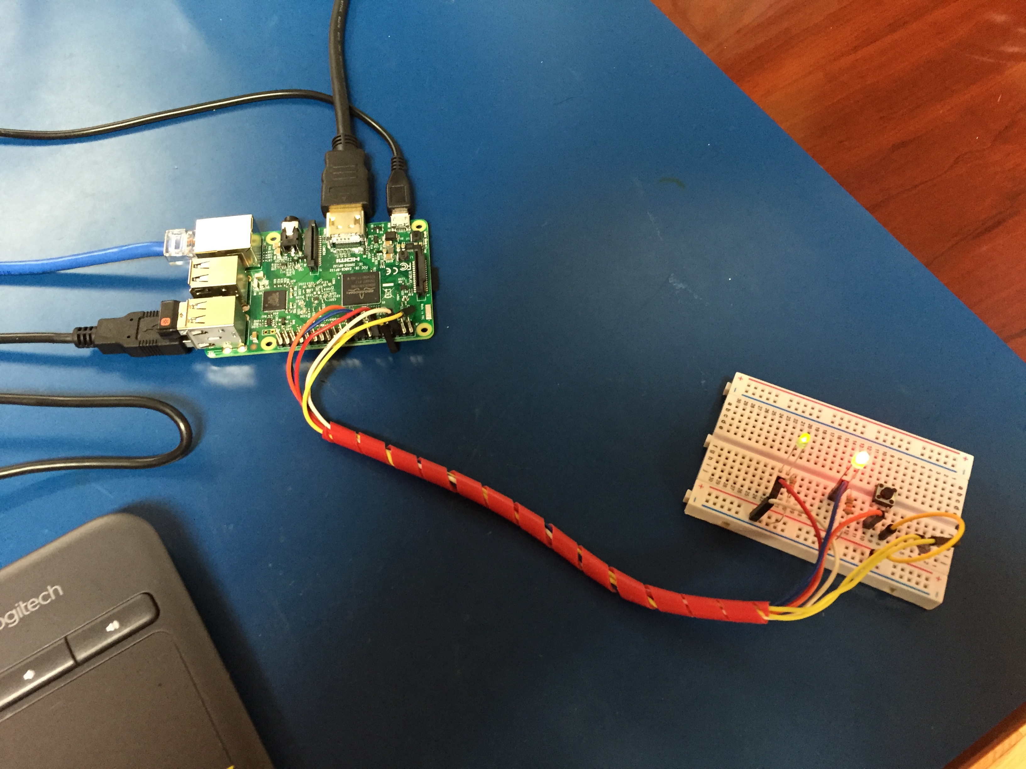\n\n ","html":"\u003ch3\u003eIntroducing \u003ca href=\"https://github.com/dchote/talkiepi\" rel=\"nofollow\"\u003etalkiepi\u003c/a\u003e.\u003c/h3\u003e\n\u003cp\u003e\u003cstrong\u003eNew post: \u003ca href=\"http://projectable.me/i-built-a-wifi-walkie-talkie-for-my-kids-now-you-can-too/\" rel=\"nofollow\"\u003ehttp://projectable.me/i-built-a-wifi-walkie-talkie-for-my-kids-now-you-can-too/\u003c/a\u003e\u003c/strong\u003e\u003c/p\u003e\n\u003cp\u003eIve had this idea for a VERY long time, to build a relatively cost effective, kid friendly, internet enabled walkie talkie. It has to be as simple as an oldschool walkie talkie to use, but it should run over wifi and allow kids to communicate with their friends in a simple and reliable way.\u003c/p\u003e\n\u003cp\u003eI recently came across a commandline mumble client written in go, called \u003ca href=\"https://github.com/layeh/barnard\" rel=\"nofollow\"\u003eBarnard\u003c/a\u003e. When I tested it, it seemed to do the job, so this weekend I ran with it and created \u003ca href=\"https://github.com/dchote/talkiepi\" rel=\"nofollow\"\u003etalkiepi\u003c/a\u003e.\u003c/p\u003e\n\u003cp\u003eThe biggest hurdle I had was finding a GPIO library that worked for my use case, and worked inside the existing barnard codebase. My initial digging with \u003ca href=\"https://github.com/stianeikeland/go-rpio\" rel=\"nofollow\"\u003ego-rpio\u003c/a\u003e was a huge headache of crashes that shouldnt happen. So I decided to go the sysfs route and settled on a slight modification to \u003ca href=\"https://github.com/brian-armstrong/gpio\" rel=\"nofollow\"\u003eBrian Armstrong\u0026#39;s\u003c/a\u003e \u003ca href=\"https://github.com/dchote/gpio\" rel=\"nofollow\"\u003ego GPIO library\u003c/a\u003e. After getting this working I realized I still had to enable the internal pullup on the button pin, so I went back to using \u003ca href=\"https://github.com/stianeikeland/go-rpio\" rel=\"nofollow\"\u003ego-rpio\u003c/a\u003e for just that.\u003c/p\u003e\n\u003cp\u003eI managed to fix the bug that stopped audio from sending when you press the button the second time. talkiepi is now fully functional! I will be working on some cleanup and housekeeping stuff (such as config files) next.\u003c/p\u003e\n\u003chr\u003e\n\u003ch3\u003eTry it yourself!\u003c/h3\u003e\n\u003cp\u003eYou can play with it on your pi and see how it goes, I do recommend using the latest raspbian image though.\u003c/p\u003e\n\u003cp\u003eFirst install the required raspbian packages \u003ccode\u003eapt-get install golang libopenal-dev libopus-dev\u003c/code\u003e. Once installed setup your \u003ccode\u003eGOPATH\u003c/code\u003e. I recommend creating a directory in your home called \u003ccode\u003egocode\u003c/code\u003e, then \u003ccode\u003eexport GOPATH=$HOME/gocode\u003c/code\u003e. You can add that to your .profile to persist it for future logins etc.\u003c/p\u003e\n\u003cp\u003eChange to your new directory \u003ccode\u003ecd $GOPATH\u003c/code\u003e and then run the following:\u003c/p\u003e\n\u003cpre\u003e\u003ccode\u003ego get github.com/layeh/gopus\ngo get github.com/dchote/talkiepi\n\u003c/code\u003e\u003c/pre\u003e\n\u003cp\u003eNow you can jump in to the code and run it:\u003c/p\u003e\n\u003cpre\u003e\u003ccode\u003ecd $GOPATH/src/github.com/dchote/talkiepi\ngo run cmd/talkiepi/main.go -server %YOUR_MUMBLE_SERVER_IP% -username %USERNAME_FOR_MUMBLE%\n\u003c/code\u003e\u003c/pre\u003e\n\u003cp\u003eIf you want to use a USB speakerphone device like I am, plug it in and run \u003ccode\u003eaplay -l\u003c/code\u003e to determine the device number, and then edit your alsa config \u003ccode\u003e/usr/share/alsa/alsa.conf\u003c/code\u003e changing the defaults to use the index of your USB device (typically 1).\u003c/p\u003e\n\u003cpre\u003e\u003ccode\u003edefaults.ctl.card 1\ndefaults.pcm.card 1\n\u003c/code\u003e\u003c/pre\u003e\n\u003chr\u003e\n\u003ch3\u003eWhats Next\u003c/h3\u003e\n\u003cp\u003eI will work on getting this stable in my free time. In short order here are the next set of features I will be adding:\u003c/p\u003e\n\u003cul\u003e\n\u003cli\u003eJoin a specified channel\u003c/li\u003e\n\u003cli\u003eConfig file for all settings\u003c/li\u003e\n\u003cli\u003eSystemd script to start on boot\u003c/li\u003e\n\u003c/ul\u003e\n\u003cp\u003eI will also work on modeling an enclosure for everything to go in!\u003c/p\u003e\n\u003cimg src=\"/content/images/2016/08/IMG_8841.JPG\" alt=\"\"\u003e\n\u003cimg src=\"/content/images/2016/08/IMG_8843.JPG\" alt=\"\"\u003e\n\u003cimg src=\"/content/images/2016/08/IMG_8844.JPG\" alt=\"\"\u003e ","excerpt":"","metaTitle":"","metaDescription":"","status":"published","featured":false,"publishedAt":"2016-08-21T17:47:08Z","authorId":"190160de54f2192bd5b8734ec8808086","authorName":"Daniel Chote","authorSlug":"daniel","heroMediaId":"9c21764682e1f36dc05c194663cea46a","projectId":"","tags":[{"id":"b529314e428273696b02c474dcf56132","name":"Raspberry Pi","slug":"raspberry-pi"},{"id":"7ad64d8755c407b3e4ca41a0a3c369c1","name":"mumble","slug":"mumble"},{"id":"b223b3e2ba0e78e7e6a6a8ff4349517d","name":"talkiepi","slug":"talkiepi"}],"createdAt":"2026-10-18T13:16:27Z","updatedAt":"2026-10-18T13:16:27Z"},{"id":"9854b5687420ea45e22c86d827b8c972","siteId":"projectable","slug":"3d-printed-raspberry-pi-powered-planetarium-projector-nightlight-part-1","title":"3D Printed, Raspberry Pi Powered, Planetarium Projector Nightlight - Part 1","markdown":"##Introduction\nMy son was learning about stars and constellations in daycare and we realized that he is always in bed before it really gets dark outside, so I had the crazy maker-dad thought, lets build a realtime planetarium night light... \n\nThe pieces are actually pretty straight forward, big LED, LCD panel, some optics and something to make the pretty pictures (the Raspberry Pi v3). I will use the Pi's GPIO to switch the LED (via MOSFET) and detect light level in the room (via LDR).\n\n##Parts\n* [Raspberry Pi v3](https://www.adafruit.com/products/3055)\n* [800x480 5\" LCD Panel](https://www.adafruit.com/products/1680) (or cheap ebay one)\n* [Adafruit TFP401 HDMI Decoder](https://www.adafruit.com/products/2218)\n* [20W Cool White LED](https://www.amazon.com/gp/product/B00D13DQHM/ref=oh_aui_detailpage_o03_s00?ie=UTF8\u0026psc=1)\n* [Boost Converter to power LED](https://www.amazon.com/gp/product/B00DWX8PM2/ref=oh_aui_detailpage_o01_s00?ie=UTF8\u0026psc=1)\n* [Headsink and Lens for LED](https://www.amazon.com/gp/product/B01D1LD68C/ref=oh_aui_detailpage_o04_s00?ie=UTF8\u0026psc=1)\n* [Fresnel lenses x2](https://www.amazon.com/gp/product/B00B0HW99M/ref=oh_aui_detailpage_o05_s00?ie=UTF8\u0026psc=1)\n\nYou will need to find something to use as a collimating/triplet lens. I ended up taking one from a cheap Chinese LED projector, as the entire projector cost less than a lot of the other options I could find. \"Why not use a cheap Chinese projector...\" Yeah, yeah, the issue I have was I wanted the crispest image possible, and full control over the throw distance. You could very well skip building your own projector and just go with a Raspberry Pi and cheap projector and call it a day, but you will end up with 1080p input scaled down to whatever crappy resolution the projector does natively, and the kicker is that the projector will likely not run at its native resolution over hdmi, giving you a blurry and out of focus looking star map. Native resolution all-the-way man... Hence the TFP401+800x480 5\" LCD panel.\n\n--------\n\n##Software\nFor software there are a couple of solutions that will run natively on a Pi, but I chose [Stellarium](http://www.stellarium.org) due to its insane flexibility.\n\n**And on to the guide...** Firstly, get Raspbian Lite working on your Pi. At this point we don't want any X stuff, we want just the base Lite Raspbian distro installed on an SD card.\n\nAfter we have a working Raspbian copy running on our Pi, we can get some base things in place...\n\nSetup the Stellarium user:\n```\nadduser --disabled-password --disabled-login --gecos \"\" stellarium\nusermod -a -G cdrom,audio,video,plugdev,users,dialout,dip,input stellarium\n```\n\nInstall the required system packages:\n```\napt-get install --no-install-recommends raspi-gpio xcompmgr dbus-x11 libgl1-mesa-dri xserver-xorg xinit bzr qtmultimedia5-dev\n```\n\nOnce you have installed these packages, you should run `raspi-config` set your timezone and locale information (this is important, as Stellarium will use it) and then **enable the GL Driver** (under advanced). Once enabled, you will be prompted to reboot your Pi, do so and then continue.\n\nEdit `/etc/kbd/config` and `/etc/X11/xinit/xinitrc` to stop your screen from turning off.\n\n/etc/kbd/config\n```\nBLANK_TIME=0\nBLANK_DPMS=off\nPOWERDOWN_TIME=0\n```\n/etc/X11/xinit/xinitrc\n```\nxset s noblank\nxset s off\nxset -dpms\n```\n\n--------\n\nNow to get Stellarium working. I had issues with font corruption with the standard Raspbian package of Stellarium, so I built it from source.\n\nInstall the Stellarium build dependancies:\n```\napt-get build-dep stellarium\n```\n\nCheckout Stellarium using bzr (*note: this takes a while*):\n```\ncd /usr/src\nbzr co lp:stellarium stellarium\n```\n\nSwitch to the a revision that works, when I tried HEAD wouldn't compile.\n```\ncd stellarium\nbzr branch -r8418\n```\n\nNow build Stellarium:\n```\nmkdir -p builds/unix\ncd builds/unix\ncmake ../..\nmake -j4\nmake install\n```\n\n--------\n\nNext we can setup a systemd service to start Stellarium on boot, create a file `/etc/systemd/system/stellarium.service` and paste the following:\n```\n[Unit]\nDescription = Stellarium\nAfter = systemd-user-sessions.service network.target sound.target\n\n[Service]\nUser = stellarium\nGroup = stellarium\nType = simple\nExecStart = /usr/bin/xinit /usr/bin/dbus-launch --exit-with-session /usr/local/bin/stellarium -t -- :0 -s 0 dpms -nolisten tcp vt7\nRestart = on-abort\nRestartSec = 5\n\n[Install]\nWantedBy = multi-user.target\n```\nNote: When building Stellarium by hand, it will be at `/usr/local/bin/stellarium` if you are using the package it will be `/usr/bin/stellarium` instead.\n\nNow you should test to ensure Stellarium works, you can do this by running `service stellarium start`. If something happens, carry on. If it breaks, let me know and I'll fix my guide! 😬\n\n\n\nAt this point you can play around with Stellarium, I suggest setting your location and FOV, enable/disable things that you may or may not want, and then save defaults. Once you are happy with everything, quit and continue with this guide.\n\n--------\n\nNow we are going to fine tune Stellarium and Raspbian for the 800x480 LCD panel, if you don't want to do that, consider yourself done!\n\nYou will want to edit Stellarium's config file, which should now be located at `/home/stellarium/.stellarium/config.ini`. These are the settings to change:\n\n```\nfullscreen = true\nscreen_w = 800\nscreen_h = 480\n```\n\nEdit the linux kernel boot parameters in `/boot/cmdline.txt` to force our 800x480 resolution by appending `video=800x480` after `rootwait`.\n\nAnd using the instructions from Adafruit's guide [here](https://learn.adafruit.com/adafruit-5-800x480-tft-hdmi-monitor-touchscreen-backpack/raspberry-pi-config). We edit `/boot/config.txt` to look like this:\n\n```\n#gpu_mem=256\n\n# uncomment if you get no picture on HDMI for a default \"safe\" mode\n#hdmi_safe=1\n\n# uncomment this if your display has a black border of unused pixels visible\n# and your display can output without overscan\n#disable_overscan=1\n\n# uncomment the following to adjust overscan. Use positive numbers if console\n# goes off screen, and negative if there is too much border\n#overscan_left=16\n#overscan_right=16\n#overscan_top=16\n#overscan_bottom=16\n\n# uncomment to force a console size. By default it will be display's size minus\n# overscan.\n#framebuffer_width=800\n#framebuffer_height=480\n\n# uncomment if hdmi display is not detected and composite is being output\nhdmi_force_hotplug=1\n\n# uncomment to force a specific HDMI mode (here we are forcing 800x480!)\nhdmi_group=2\nhdmi_mode=1\nhdmi_mode=87\nhdmi_cvt=800 480 60 6 0 0 0\n\n#max_usb_current=1\n\n# uncomment to force a HDMI mode rather than DVI. This can make audio work in\n# DMT (computer monitor) modes\n#hdmi_drive=2\n\n# uncomment to increase signal to HDMI, if you have interference, blanking, or\n# no display\n#config_hdmi_boost=4\n\n# uncomment for composite PAL\n#sdtv_mode=2\n\n#uncomment to overclock the arm. 700 MHz is the default.\n#arm_freq=800\n\n# for more options see http://elinux.org/RPi_config.txt\ndtoverlay=vc4-kms-v3d\n```\n\nOnce you have made these changes, you can reboot, and your Pi should restart in native 800x480 and boot right in to Stellarium!\n\n\n\nThis concludes part 1 of the guide, part 2 will go over my build progress thus far, including 3d models of the prototype components I have designed.\n\n\n\n","html":"\u003ch2\u003eIntroduction\u003c/h2\u003e\n\u003cp\u003eMy son was learning about stars and constellations in daycare and we realized that he is always in bed before it really gets dark outside, so I had the crazy maker-dad thought, lets build a realtime planetarium night light...\u003c/p\u003e\n\u003cp\u003eThe pieces are actually pretty straight forward, big LED, LCD panel, some optics and something to make the pretty pictures (the Raspberry Pi v3). I will use the Pi\u0026#39;s GPIO to switch the LED (via MOSFET) and detect light level in the room (via LDR).\u003c/p\u003e\n\u003ch2\u003eParts\u003c/h2\u003e\n\u003cul\u003e\n\u003cli\u003e\u003ca href=\"https://www.adafruit.com/products/3055\" rel=\"nofollow\"\u003eRaspberry Pi v3\u003c/a\u003e\u003c/li\u003e\n\u003cli\u003e\u003ca href=\"https://www.adafruit.com/products/1680\" rel=\"nofollow\"\u003e800x480 5\u0026#34; LCD Panel\u003c/a\u003e (or cheap ebay one)\u003c/li\u003e\n\u003cli\u003e\u003ca href=\"https://www.adafruit.com/products/2218\" rel=\"nofollow\"\u003eAdafruit TFP401 HDMI Decoder\u003c/a\u003e\u003c/li\u003e\n\u003cli\u003e\u003ca href=\"https://www.amazon.com/gp/product/B00D13DQHM/ref=oh_aui_detailpage_o03_s00?ie=UTF8\u0026amp;psc=1\" rel=\"nofollow\"\u003e20W Cool White LED\u003c/a\u003e\u003c/li\u003e\n\u003cli\u003e\u003ca href=\"https://www.amazon.com/gp/product/B00DWX8PM2/ref=oh_aui_detailpage_o01_s00?ie=UTF8\u0026amp;psc=1\" rel=\"nofollow\"\u003eBoost Converter to power LED\u003c/a\u003e\u003c/li\u003e\n\u003cli\u003e\u003ca href=\"https://www.amazon.com/gp/product/B01D1LD68C/ref=oh_aui_detailpage_o04_s00?ie=UTF8\u0026amp;psc=1\" rel=\"nofollow\"\u003eHeadsink and Lens for LED\u003c/a\u003e\u003c/li\u003e\n\u003cli\u003e\u003ca href=\"https://www.amazon.com/gp/product/B00B0HW99M/ref=oh_aui_detailpage_o05_s00?ie=UTF8\u0026amp;psc=1\" rel=\"nofollow\"\u003eFresnel lenses x2\u003c/a\u003e\u003c/li\u003e\n\u003c/ul\u003e\n\u003cp\u003eYou will need to find something to use as a collimating/triplet lens. I ended up taking one from a cheap Chinese LED projector, as the entire projector cost less than a lot of the other options I could find. \u0026#34;Why not use a cheap Chinese projector...\u0026#34; Yeah, yeah, the issue I have was I wanted the crispest image possible, and full control over the throw distance. You could very well skip building your own projector and just go with a Raspberry Pi and cheap projector and call it a day, but you will end up with 1080p input scaled down to whatever crappy resolution the projector does natively, and the kicker is that the projector will likely not run at its native resolution over hdmi, giving you a blurry and out of focus looking star map. Native resolution all-the-way man... Hence the TFP401+800x480 5\u0026#34; LCD panel.\u003c/p\u003e\n\u003chr\u003e\n\u003ch2\u003eSoftware\u003c/h2\u003e\n\u003cp\u003eFor software there are a couple of solutions that will run natively on a Pi, but I chose \u003ca href=\"http://www.stellarium.org\" rel=\"nofollow\"\u003eStellarium\u003c/a\u003e due to its insane flexibility.\u003c/p\u003e\n\u003cp\u003e\u003cstrong\u003eAnd on to the guide...\u003c/strong\u003e Firstly, get Raspbian Lite working on your Pi. At this point we don\u0026#39;t want any X stuff, we want just the base Lite Raspbian distro installed on an SD card.\u003c/p\u003e\n\u003cp\u003eAfter we have a working Raspbian copy running on our Pi, we can get some base things in place...\u003c/p\u003e\n\u003cp\u003eSetup the Stellarium user:\u003c/p\u003e\n\u003cpre\u003e\u003ccode\u003eadduser --disabled-password --disabled-login --gecos \u0026#34;\u0026#34; stellarium\nusermod -a -G cdrom,audio,video,plugdev,users,dialout,dip,input stellarium\n\u003c/code\u003e\u003c/pre\u003e\n\u003cp\u003eInstall the required system packages:\u003c/p\u003e\n\u003cpre\u003e\u003ccode\u003eapt-get install --no-install-recommends raspi-gpio xcompmgr dbus-x11 libgl1-mesa-dri xserver-xorg xinit bzr qtmultimedia5-dev\n\u003c/code\u003e\u003c/pre\u003e\n\u003cp\u003eOnce you have installed these packages, you should run \u003ccode\u003eraspi-config\u003c/code\u003e set your timezone and locale information (this is important, as Stellarium will use it) and then \u003cstrong\u003eenable the GL Driver\u003c/strong\u003e (under advanced). Once enabled, you will be prompted to reboot your Pi, do so and then continue.\u003c/p\u003e\n\u003cp\u003eEdit \u003ccode\u003e/etc/kbd/config\u003c/code\u003e and \u003ccode\u003e/etc/X11/xinit/xinitrc\u003c/code\u003e to stop your screen from turning off.\u003c/p\u003e\n\u003cp\u003e/etc/kbd/config\u003c/p\u003e\n\u003cpre\u003e\u003ccode\u003eBLANK_TIME=0\nBLANK_DPMS=off\nPOWERDOWN_TIME=0\n\u003c/code\u003e\u003c/pre\u003e\n\u003cp\u003e/etc/X11/xinit/xinitrc\u003c/p\u003e\n\u003cpre\u003e\u003ccode\u003exset s noblank\nxset s off\nxset -dpms\n\u003c/code\u003e\u003c/pre\u003e\n\u003chr\u003e\n\u003cp\u003eNow to get Stellarium working. I had issues with font corruption with the standard Raspbian package of Stellarium, so I built it from source.\u003c/p\u003e\n\u003cp\u003eInstall the Stellarium build dependancies:\u003c/p\u003e\n\u003cpre\u003e\u003ccode\u003eapt-get build-dep stellarium\n\u003c/code\u003e\u003c/pre\u003e\n\u003cp\u003eCheckout Stellarium using bzr (\u003cem\u003enote: this takes a while\u003c/em\u003e):\u003c/p\u003e\n\u003cpre\u003e\u003ccode\u003ecd /usr/src\nbzr co lp:stellarium stellarium\n\u003c/code\u003e\u003c/pre\u003e\n\u003cp\u003eSwitch to the a revision that works, when I tried HEAD wouldn\u0026#39;t compile.\u003c/p\u003e\n\u003cpre\u003e\u003ccode\u003ecd stellarium\nbzr branch -r8418\n\u003c/code\u003e\u003c/pre\u003e\n\u003cp\u003eNow build Stellarium:\u003c/p\u003e\n\u003cpre\u003e\u003ccode\u003emkdir -p builds/unix\ncd builds/unix\ncmake ../..\nmake -j4\nmake install\n\u003c/code\u003e\u003c/pre\u003e\n\u003chr\u003e\n\u003cp\u003eNext we can setup a systemd service to start Stellarium on boot, create a file \u003ccode\u003e/etc/systemd/system/stellarium.service\u003c/code\u003e and paste the following:\u003c/p\u003e\n\u003cpre\u003e\u003ccode\u003e[Unit]\nDescription = Stellarium\nAfter = systemd-user-sessions.service network.target sound.target\n\n[Service]\nUser = stellarium\nGroup = stellarium\nType = simple\nExecStart = /usr/bin/xinit /usr/bin/dbus-launch --exit-with-session /usr/local/bin/stellarium -t -- :0 -s 0 dpms -nolisten tcp vt7\nRestart = on-abort\nRestartSec = 5\n\n[Install]\nWantedBy = multi-user.target\n\u003c/code\u003e\u003c/pre\u003e\n\u003cp\u003eNote: When building Stellarium by hand, it will be at \u003ccode\u003e/usr/local/bin/stellarium\u003c/code\u003e if you are using the package it will be \u003ccode\u003e/usr/bin/stellarium\u003c/code\u003e instead.\u003c/p\u003e\n\u003cp\u003eNow you should test to ensure Stellarium works, you can do this by running \u003ccode\u003eservice stellarium start\u003c/code\u003e. If something happens, carry on. If it breaks, let me know and I\u0026#39;ll fix my guide! 😬\u003c/p\u003e\n\u003cimg src=\"/content/images/2016/08/IMG_8455.JPG\" alt=\"\"\u003e\n\u003cp\u003eAt this point you can play around with Stellarium, I suggest setting your location and FOV, enable/disable things that you may or may not want, and then save defaults. Once you are happy with everything, quit and continue with this guide.\u003c/p\u003e\n\u003chr\u003e\n\u003cp\u003eNow we are going to fine tune Stellarium and Raspbian for the 800x480 LCD panel, if you don\u0026#39;t want to do that, consider yourself done!\u003c/p\u003e\n\u003cp\u003eYou will want to edit Stellarium\u0026#39;s config file, which should now be located at \u003ccode\u003e/home/stellarium/.stellarium/config.ini\u003c/code\u003e. These are the settings to change:\u003c/p\u003e\n\u003cpre\u003e\u003ccode\u003efullscreen = true\nscreen_w = 800\nscreen_h = 480\n\u003c/code\u003e\u003c/pre\u003e\n\u003cp\u003eEdit the linux kernel boot parameters in \u003ccode\u003e/boot/cmdline.txt\u003c/code\u003e to force our 800x480 resolution by appending \u003ccode\u003evideo=800x480\u003c/code\u003e after \u003ccode\u003erootwait\u003c/code\u003e.\u003c/p\u003e\n\u003cp\u003eAnd using the instructions from Adafruit\u0026#39;s guide \u003ca href=\"https://learn.adafruit.com/adafruit-5-800x480-tft-hdmi-monitor-touchscreen-backpack/raspberry-pi-config\" rel=\"nofollow\"\u003ehere\u003c/a\u003e. We edit \u003ccode\u003e/boot/config.txt\u003c/code\u003e to look like this:\u003c/p\u003e\n\u003cpre\u003e\u003ccode\u003e#gpu_mem=256\n\n# uncomment if you get no picture on HDMI for a default \u0026#34;safe\u0026#34; mode\n#hdmi_safe=1\n\n# uncomment this if your display has a black border of unused pixels visible\n# and your display can output without overscan\n#disable_overscan=1\n\n# uncomment the following to adjust overscan. Use positive numbers if console\n# goes off screen, and negative if there is too much border\n#overscan_left=16\n#overscan_right=16\n#overscan_top=16\n#overscan_bottom=16\n\n# uncomment to force a console size. By default it will be display\u0026#39;s size minus\n# overscan.\n#framebuffer_width=800\n#framebuffer_height=480\n\n# uncomment if hdmi display is not detected and composite is being output\nhdmi_force_hotplug=1\n\n# uncomment to force a specific HDMI mode (here we are forcing 800x480!)\nhdmi_group=2\nhdmi_mode=1\nhdmi_mode=87\nhdmi_cvt=800 480 60 6 0 0 0\n\n#max_usb_current=1\n\n# uncomment to force a HDMI mode rather than DVI. This can make audio work in\n# DMT (computer monitor) modes\n#hdmi_drive=2\n\n# uncomment to increase signal to HDMI, if you have interference, blanking, or\n# no display\n#config_hdmi_boost=4\n\n# uncomment for composite PAL\n#sdtv_mode=2\n\n#uncomment to overclock the arm. 700 MHz is the default.\n#arm_freq=800\n\n# for more options see http://elinux.org/RPi_config.txt\ndtoverlay=vc4-kms-v3d\n\u003c/code\u003e\u003c/pre\u003e\n\u003cp\u003eOnce you have made these changes, you can reboot, and your Pi should restart in native 800x480 and boot right in to Stellarium!\u003c/p\u003e\n\u003cimg src=\"/content/images/2016/08/IMG_8605.JPG\" alt=\"\"\u003e\n\u003cp\u003eThis concludes part 1 of the guide, part 2 will go over my build progress thus far, including 3d models of the prototype components I have designed.\u003c/p\u003e\n\u003cimg src=\"/content/images/2016/08/IMG_8782-2.JPG\" alt=\"\"\u003e\n\u003cimg src=\"/content/images/2016/08/IMG_8780-1.JPG\" alt=\"\"\u003e\n\u003cimg src=\"/content/images/2016/08/IMG_8785-1.JPG\" alt=\"\"\u003e","excerpt":"","metaTitle":"","metaDescription":"","status":"published","featured":false,"publishedAt":"2016-08-10T20:05:10Z","authorId":"190160de54f2192bd5b8734ec8808086","authorName":"Daniel Chote","authorSlug":"daniel","heroMediaId":"","projectId":"","tags":[{"id":"b529314e428273696b02c474dcf56132","name":"Raspberry Pi","slug":"raspberry-pi"},{"id":"e58b4788e99c9f53befd1e47b8073250","name":"3D Printing","slug":"3d-printing"},{"id":"298a0af2ab978a60d089e90666ea07dc","name":"Stellarium","slug":"stellarium"},{"id":"af2996855a33f2b6e91cee4153e3ed0b","name":"LED","slug":"led"}],"createdAt":"2026-10-18T13:16:27Z","updatedAt":"2026-10-18T13:16:27Z"}],"site":{"id":"projectable","theme":"projectable","title":"Daniel Chote's Project Blog","description":"Software Development, Hardware Hacking, Sim Racing, Multirotors and Robots!","timezone":"America/New_York","postsPerPage":10,"logoMediaId":"21557257b3f2ecc4b3fa875b808097a7","coverMediaId":"25f1417193daeb2af73861aaa0dd17fd","copyright":"© Daniel Chote","twitterUrl":"https://twitter.com/dchote","linkedinUrl":"https://www.linkedin.com/in/dchote","googleTagId":"G-07GJBQVM38","hosts":[{"host":"new.projectable.me","canonical":false},{"host":"projectable.me","canonical":true},{"host":"www.projectable.me","canonical":false}]},"tag":{"name":"Raspberry Pi","slug":"raspberry-pi"},"tagId":"b529314e428273696b02c474dcf56132","total":7}